This unique circuit allows you to create many different sound effect outputs simply by moving your hands over a couple of light dependent resistors, by varying the intensity of incident light over the LDRs.
By Ramesh Powar
The generator has two different cells LDRs that control a sound - burst oscillator circuit. One LDR controls the tone while the other controls the burst duration. All you have to do is sweep your hands over the LDRs to produce a variety of sounds.
Basic Working Principle
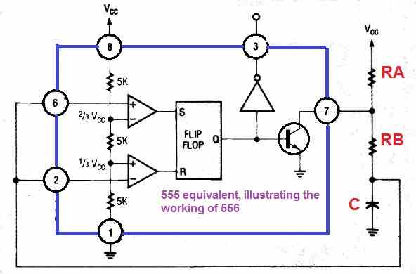
To generate the unusual noises, the tone-burst oscillator circuit employs a 556 timer IC with positive feedback. The 556 device comprises a couple of entirely independent 555 ICs, and the output of one IC 555 controls the oscillation period or burst duration of the other in our operation.
The discharge delay is the duration it requires for the voltage on C to decrease from 2/3 Vcc to 1/3 Vcc (tD). When the 555's flip-flop reaches 1/3 Vcc, it resets and permits C to charge between RA and RB. The charge time is the time required for C to charge to 2/3 Vcc (tc).
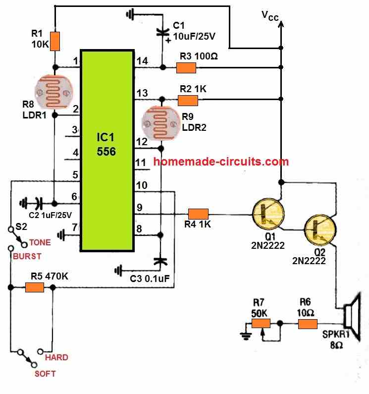
The 555's flip-flop sets as soon as this threshold of charge is achieved, causing C to discharge across RB, so that the cycle keeps repeating. The entire circuit for our light-controlled sound effect generator circuit is shown in Figure below.

You'll see that a couple of photocells, or LDRs, are used: R8 and R9. A photocell is essentially a resistor whose magnitude is proportional to the quantity of illumination it is subjected to.
The intensity of the light has an inverse relationship with its resistance. A standard LDR can decrease to 100 ohms in intense light, but it can quickly approach 500 kilohms during darkness.
In case we substitute RB the figure below, with a photocell LDR, the lowest and highest resistance values (100 ohms and 500K) could be determined by calculating the range of frequencies which the 555 can produce, as indicated below:

Cycle time = 0.7(RA +RB)C +(0.7 x RB x C)
The duration of the operating cycle can be = 1.4 × RB x C in case RB is very minimal. If C is 0.1uF, the maximum cycle time duration for a frequency of 0.7 hertz is 700 milliseconds, while the smallest cycle time interval for a frequency of 5000 hertz is 0.2 milliseconds.
This circuit's power source must be capable of delivering between 5 V and 15 V DC, and this should be capable of delivering at approximately 1 amp at 5 volts. While the circuit is under no-load situations, the output must never surpasses 15 volts or the circuit will be damaged.
Circuit Description
Since the frequency and burst duration of the circuit are modulated by brightness, the circuit must be operated in an environment having abundant overhead light. S3 may be opened and closed to vary the tone burst function.
This either connects the burst timer's output to the tone oscillator's reset directly, or swaps the direct connection with resistor R5 for an entirely new sound effect.
The burst function is disabled by unlocking S2, and the clean tones that follow may be manipulated by floating one hand over R9. It's important to keep in mind that the quantity of light impacting LDRs R8 and R9 is crucial for effective circuit performance.
Since LDR sensitivity varies, one needs to adjust the light to the correct frequency range. If the modification isn't enough, you can change the values of timer capacitors C2 and C3 to increase the range of potential frequencies.
Different sound tones that can be generated
Here's a list of different sound effects you can produce, along with guidelines of how to do it:
The sound of police sirens: Move up and down your right hand within 1 and 3 inches around R9 once each second with the 'TONE/BURST switch S2 set to tone.
The old automobile has started: Set the HARD/SOFT switch S3 to hard and the TONE/BURST switch S2 to burst. Lift your left hand (or whichever hand is at R8) steadily over the LDRs using your right and left hands.
Plane taking off: Bring your right hand near LDR R9 and gently lift it. Set TONE/ BURST switch S2 to tone. Stop when you reach 2 inches.
Aliens have landed: Set the HARD / SOFT switch S3 to hard and the TONE /BURST switch S2 to burst.
Put your hands up over your head and gently place them upon that LDRs.
The sound of birds chirping: Set the HARD/SOFT switch S3 to hard and the TONE/BURST switch S2 to burst. Placing your left hand 2 inches over photocell LDR R8 is a good idea. Open your right hand's fingers and move them across LDR R9 from about 2 inches away.
The sound of ghosts wailing: Set the HARD/SOFT switch to soft and the TONE/BURST switch to tone. Lift your right hand over the LDR R9 between 1 and 3 inches while fluttering it.
Frankenstein Sound Effect: Adjust the HARD/SOFT switch S3 to soft and the TONE/BURST switch S2 to burst. Put your hands up over your head and gradually bring them until the LDRs are at touching distance.
Elevate your left hand to about 3 inches above the switch, next drop to within about 1 inch. Lift your right hand 3 inches simultaneously. Keep repeating the procedure.
Nuclear radiation alert: Select the 'DONE/BURST' option. S2 is the second switch. Configure HARD/SOFT switch S3 to hard on burst. Curve your right hand 1 inch over LDR R9, subsequently 2 inches over LDR R8.
Foghorn Alarm Sound: Configure TONE /BURST switch S2 to burst and HARD /SOFT switch S3 to hard for foghorn sound effect. Put your right hand over LDR R9. Keeping your left hand over LDR R8 seems to be a good idea.
Smoke Detector Alarm: Adjust the TONE/BURST switch S2 to burst and the HARD/SOFT switch S3 to hard to get the smoke detector alarm sound. R9 should be 3 inches over your right hand, and R8 should be 1 inch away from your left hand.
This light-controlled sound effect generator circuit is essentially a musical device, and the audio quality is determined by the performer's talent and imagination. If you've ever wanted to build a circuit that could generate unique sound effects, this circuit project is just for you.
Hi
I tried Hall sensors, it is affected as N and S direction. This shouldn’t happen.
Is it possible to design a project with no holes, just to pinpoint the metal exactly (center point without error)?
Best regards
You can possibly try metals detector for your purpose. Here’s the page which provides more info about it.
https://www.homemade-circuits.com/?s=metal+detector
Hi,
First of all, thank you very much for your reply. This project will be a project that needs to locate the exact location of the 3 mm hole on a metal bar behind the 4 cm concrete. I need your support for this project.
You are welcome….Metal can be detected under concrete but I am not sure how a hole on a metal; can be detected. I do not have any such circuit with me at this moment.
Hi
I follow your work with interest.
I need your help for a project…. I want to locate the 3 mm hole on a rod-shaped netal at a distance of 4 cm. Can you help me with my project in this regard?
Best regards
Turgut POZAM
ISTANBUL – TURKEY
ISTANBUL TURKEY
Hi, I appreciate your interest.
3mm hole can be seen through vision, so why a detector is required?
Sorry I do not have this circuit idea with me at this moment.