In this article we are going to see what is a light to frequency converter circuit, how it works, how to use it in a project, and its specifications.
No matter which category you belong to, professional, hobbyist, engineer or student, modular components always reduce half of our headache while designing circuits.
They eliminate the need for designing special circuits and reduce cost effectively. One such modular component is TSL235R light to frequency converter.
What is light to frequency converter (TSL235R)?
This modular component is basically an IC which converts light intensity into frequency with 50% duty cycle.
The light intensity and frequency are proportional.
When ambient or any external light intensity rises, the output frequency increases and vice versa.
TSL235R is three legged device looks pretty much like a transistor with a translucent casing.
It comes in two forms, one is surface mount and other is common PCB mount type.
The main advantage of this IC is that no external component is required to generate frequency; it can be directly interfaced to any microcontroller or microprocessor.
It has tiny bulged lens in front of the module for focusing the light and back side is flat. It is very sensitive that it detects tiny changes in light.

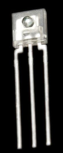
Specification overview:
TSL235R can be powered from 2.7 V to 5.5 V (5 V nominal).
It has wide range of light response from 320nm to 1050nm which covers from ultraviolet to visible light. It has working temperature ranging from -25 degree Celsius to +70 degree Celsius.
It has temperature coefficient of 150 ppm per degree Celsius. The maximum frequency it can deliver is 100 KHz and minimum frequency is in the range of few 100 Hz.
The output duty cycle is strictly calibrated 50%. It measures 19.4mm in length including terminal and 4.6mm wide.
A capacitor ranging from 0.01 mfd to 0.1 mfd must be connected from its power supply terminal and the capacitor and TLS235R must close as possible.
How it works?

It combines two components, one is a silicon photodiode and the other is current to frequency converter (CFC). The CFC is a circuitry which converts current parameter to frequency parameter.
The current flow through photodiode is proportional to light intensity.
The current to frequency converter (CFC) measure the amount of current flow through the photodiode.
When the current flow through the photodiode increases; CFC raises it frequency and vice versa is also true. Thus we get an indirect conversion from light to frequency.
How and where to use it?
You may use TSL235R where you are working with any light based project such as:
· You may use it for measuring ambient light intensity such as lux meter.
· You may couple a LED and TSL235R for feedback circuit in inverter where output need to be stabilized regardless of the connected load.
· It can be used in motion detector, where any change in light intensity can be detected.
· It can be utilized in security system.
· It can be utilized in automatic street light system, where fall in the frequency can be detected by a microcontroller and trigger the output.
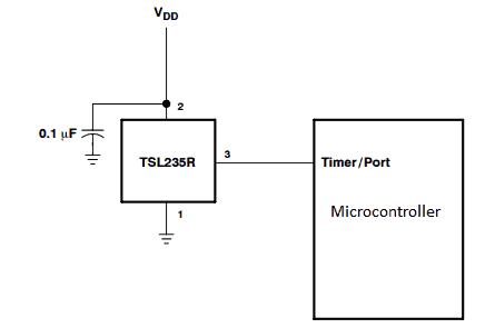
Here is an illustration how to interface it with microcontroller
The applications are unlimited when start play with it and understand in right way.
Application Circuits
In the following paragraphs I will try to explain a few interesting light frequency converter application circuit using the above explained IC TLS235R
1) Adjustable Light to Frequency Generator Circuit
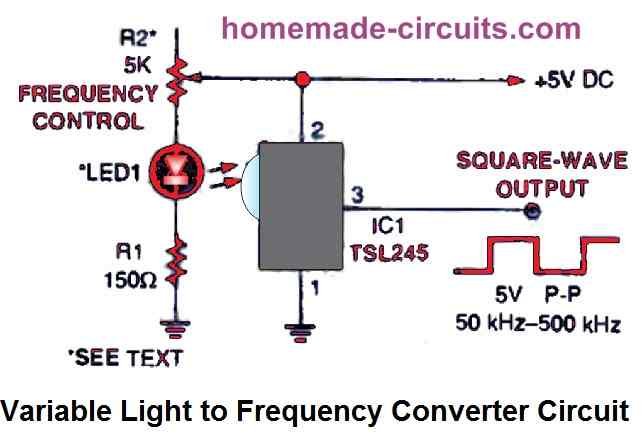
Our first design, shown above, uses the potentiometer R2 as the frequency control and produces square waves with an adjustable frequency that range from 50 kHz to around 500 kHz.
With a distance of roughly half an inch, an infrared (IR) LED with a peak power defined at 880 nm is pointed at the TSL245 input window, which is the little, convex protrusion at the front of the IC.
A light-proof container should be created to enclose the IR pair. This step is crucial since the photodiode will become useless should any external light reaches it somewhere.
The smallest amount of light that penetrates the photodiode determines the slowest running frequency of the circuit. The circuit's output frequency may be lower than 1 Hz in complete darkness. Whenever R2 is adjusted to its highest resistance level and the LED's light output is at its weakest level, the circuit operates at its lowest frequency.
By substituting R2 to a 10k resistor or 20k potentiometer, the square-wave generating circuit may be adjusted to work in the audible frequency range. Temporarily disconnect the IR LED's power and verify the output frequency if the circuit doesn't work at low frequency range.
There is a strong chance that the external ambient light may be hitting the photo-diode if it the frequency level is over 50 Hz. Investigate the circuit with a bright ambient light to check if the frequency has increased.
If you find nothing changing, then the enclosure may be considered perfectly sealed. However identify the light leakage and apply concealment if there is an escalation in the frequency level.
Light Dependent Tone Generator Circuit
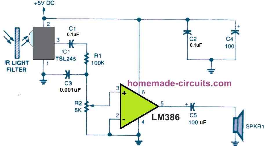
The TSL245 is employed in the circuit above as part of a light-seeking device that generates an audio output tone in accordance to the intensity of IR light striking the integrated circuit.
The IC includes an integrated IR filter, however extra filtering is still required for the circuit to function in the music frequency range under environments of standard ambient light.
A 35mm or equivalent kind of film's exposed and developed ends could be used to create an appropriate IR filter. The circuit will create a 2- to 8-kHz output signal in an environment having normal lighting if the film endings are very black and are placed on the front of the IC in as many layers as required.
The maximum operating frequency of the circuit is determined by the amount of film layers involved. The bare minimum of light that may enter the IC's photodiode will determine the lowest output frequency.
The circuit's functioning and potential applications are described below. The TSL245 generates an output in response to ambient light hitting the IC1, and this output is linked through C1, R1, and R2 to the input of an LM386 audio power amplifier IC. Higher frequencies are avoided by C3 and directed to ground.
A little 4 ohm speaker is operated by the amplifier. Waving your hand over the TSL245 will cause the output frequency of the oscillator to decrease if you wish to decrease it (or pitch). When you completely block the light with your hand or another opaque item, the sound will decrease to its lowest frequency.
Light to frequency converter using IC 555
A similar circuit can be achieved by using the IC 555 wired in an astable mode with one of its resistor replaced with an LDR, as shown below:
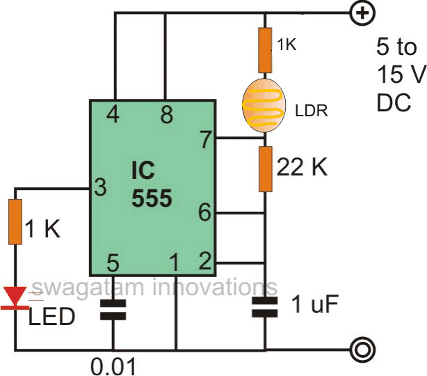
The capacitor C1 can be replaced with other values for obtaining other sets of frequency ranges, as per the application specs.
The pin3 of the IC 555 can be integrated to any desired external load or circuit, in case a TTL compatible output is required make sure to power the IC 555 with a precise 5V.
How have you designed the values of the resistors and capacitors?
Ok I see I thought you tried something similar with the led and LDR on an inverter before, I think you placed it on the control pin of the 555 IC. But I guess this is a different principle I assumed it was the same because I saw it mentioned inverter feedback in the uses section.
yes, it's a different concept and can be applied in circuits that may be dependent on frequency parameter….
Inverters are PWM based concept where frequency needs to be constant and may not be relevant to its output management or correction.
In this article it's refering to your light to frequency converter which you said can be implemented in an inverter feedback circuit, so I was saying to you that I would like to see you add it to an inverter circuit
sorry, frequency alteration cannot be used for voltage correction or for shut down operations, it's written by another author.
you might need further stages to convert the frequency into another suitable form which might enable the shut down operation in the inverter
Hello Ainsworth and Swagatam, good day.
I mention that it can be implemented in inverter's feedback circuitry. This concept is inspired from this article https://www.homemade-circuits.com/2012/05/load-independentoutput-corrected.html
Where brightness of the LED is converted to PWM . Similarly we can couple the LED and Light to frequency converter module, and the output can be interfaced to a Micro-controller where the frequency changes is sensed and appropriate PWM can be generated. This PWM is applied to GATE of the MOSFET. Thus we can keep the output stable.
Regards
Hi GR,
In my inverter voltage correction circuit, the LED intensity changes in response to inverter output voltage, whereas the above circuit is a light to frequency converter which cannot be used to satisfy the PWM correction need in any manner, unless more stages are included.
PWM is different to frequency, chnages frequency will not change PWM….I think you got confused with these two parameters.
But no issues, you will gradually learn about all these parameters as you discuss and interact more.
I hope to see you implement this with an inverter because I would like to try it.
If you can elaborate a bit would help me to understand better.