In this post I have explained how to build a line follower robot circuit using Arduino, which will run over a specifically drawn line layout and will faithfully follow it as long as it is available and traceable by its sensors.
By Navneet Sajwan
What is a Line Follower Robot
An autonomous robot is a machine that can take a series of actions as instructed by the programmer, without being manually controlled by a human being in real-time.
Line followers (LFRs) are also autonomous robot cars that are guided by one or more sensors and a black or white line path. They form the basis of modern self-driving cars.
Like every autonomous robot , line followers have a signal processing and decision making unit , sensors and actuators. If you are a beginner in robotics and want to take it up seriously, this is where you should start. Let’s begin making it.
I have used two infra-red sensors and three wheel drive for making this project. Minimum number of sensors that can be used is one and maximum of eight are sufficient for PID based line following.
Components Required:
Arduino Uno
Chassis
Two battery operated(b.o.) motors and compatible tyres
Castor ball
Two infrared sensors
Motor driver module
Power Supply
Arduino IDE software
Now, let’s have a look at our components:
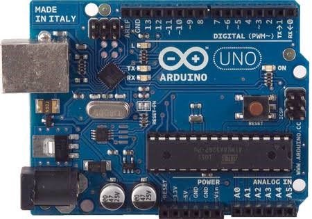
ARDUINO UNO: Imagine it as the control room of our robot .Now, there are a lot many development boards, that were considered for this project, but Arduino UNO was simply no match to others. It isn't that our protagonist was superior in terms of its multidimensional features.
If that had been the case, Raspberry Pi and Intel Edison would have smacked it between the eyes. The most compelling arguments that led to the selection of Arduino UNO were formed by the combination of features, price, size and requirement for the project.
Some relevant reasons were:
SIZE : It is quite small compared to Atmega16 or Atmega8 based development boards, consumes a little space on chassis, so you get a compact and handy bot.
This really matters in robotics competitions. Trust me you would hate roaming around with that big ugly bot, changing venues all day.
Smaller the size , faster the robot and more efficient the turns.
BEST PROTOTYPING BOARD: Undoubtedly, Arduino UNO has the best combination of features for prototyping. Once your circuits are in place and your project works perfect you can replace it with something smaller and cheaper like Arduino Nano and Attiny85 ic.
For those ,making line follower for college projects , I suggest replacing UNO with Nano at the end.
CHASSIS: It is the frame that holds the all the components in position. There are a few points to consider while buying a new chassis ,
It should be lightweight and strong.
For projects, it's better if you buy one from market. But If you are preparing for competition, I strongly suggest you customize your own ,keeping in mind the dimensions and the requirements of the competition.
Choose a plastic or wooden chassis. When metallic frames come in contact with Arduino , a number of pins get shorted. This is a big factor to focus on while looking out for chassis.
Keep your chassis as low as possible - this gives stability to the bot.
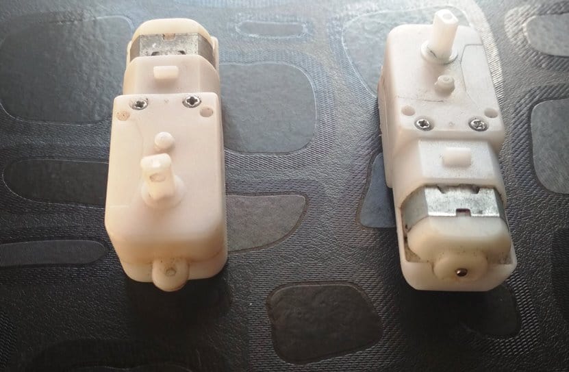
MOTORS: Use light weight battery operated (B.O.) d.c. motors.
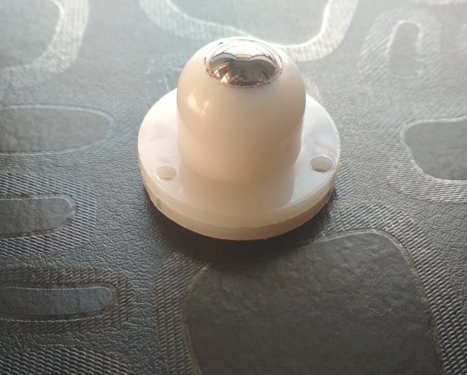
CASTOR BALL: Normal wheels provide translatory motion along a single axis but a castor ball is designed to move along any direction on surface. It gives us three wheel drive.
The reason for preferring three wheel drive over 4 wheels is because of its comparatively faster turning action. You might have noticed the cycle rickshaws piercing through the traffic like reptiles. Same is the case of our robot.
SENSORS: It is a device that detects or measures any physical parameter of our environment and converts it into electric signals. In this case the parameter detected is infra-red rays.
Sensors are highly fundamental for any robot. Well, if arduino is our bot’s brain, sensors might as well play the role of eyes. Here are a few things about sensors:
The sensors must be oriented in a way that led(s) face the ground.
Should be placed at the front end of your bot.
Minimum spacing between them must be greater than the width of the black line.
MOTOR DRIVER BOARD : Motor-drivers are buffer circuits that take up low voltage signals to power up the motors that require higher voltage.
In our case, Arduino can provide sufficient voltage to drive the motors but it cannot provide ample current. Arduino UNO’s 5v and GND pins have current rating of 200mA while any GPIO pin has rating of 40 mA. This is way lower than the starting and stall currents motors we need .
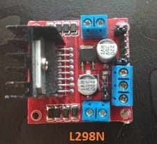
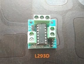
There are two motor drivers that I prefer for this project: L298N and L293D. Both of them are equally suitable for making this project.
Though, L293D is comparatively cheaper but has a low current rating. Their connections are nearly the same. Since, I have given the connections for both, it is totally up to you how you make your bot.
POWER SUPPLY:
Use a 12 v adapter or a battery (not more than 12 volts).
Placement of components (from front to back end):
Sensors at the head of your bot.
Castor wheel in the middle.
Motors and tyres in one line at the back.
Connections:
SENSORS to ARDUINO:
Connect the sensor pin to arduino pin as shown,
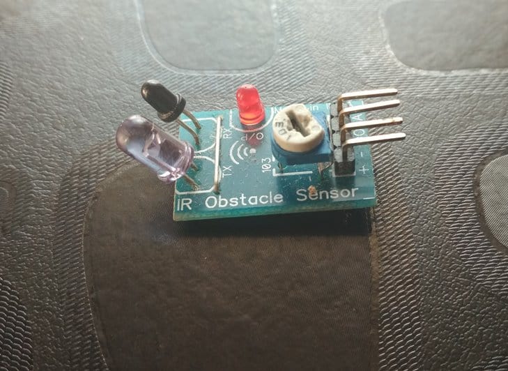
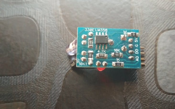
| Sensor pin | Arduino pin |
| VCC(5v) | 5V |
| GND(G) | GND |
| LEFT SENSOR OUT(DO) | pin 6 |
| RIGHT SENSOR OUT(DO) | pin 7 |
Note :To check if your sensors are powered up, point your cell phone camera at the IR transmitter led. You will see led glowing on screen which cannot be seen by our naked eyes. Some modern cell phone cameras have Infra red filter. So, please take that into account.
MOTOR to MOTOR DRIVER:
Each motor has two terminals which need to be connected to motor driver. Never try to connect them directly to arduino. Looking from the back of your bot , with motors near to you and sensors away, connect them as follows:
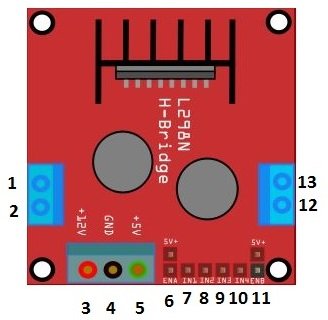
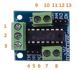
| MOTOR | L298N | L293D |
| LEFT MOTOR | PIN 1 AND 2 | PIN 7 AND 8 |
| RIGHT MOTOR | PIN 13 AND 14 | PIN 9 AND 10 |
MOTOR DRIVER to ARDUINO UNO:

| MOTOR DRIVER(L298N) | ARDUINO UNO |
| PIN 4 | VIN |
| PIN 5 | GND |
| PIN 6 | 5V |
| PIN 8 & PIN 9 | PIN 3 & PIN 9 |
| PIN 10 & PIN 11 | PIN 5 & PIN 10 |
| PIN 7 & PIN 12 | 5V |

| MOTOR DRIVER(L293D) | ARDUINO UNO |
| PIN 3 | VIN |
| PIN 2 | GND |
| PIN 1 | 5V |
| PIN 5 AND PIN 6 | PIN 3 & PIN 9 |
| PIN 11 AND PIN 12 | PIN 5 & PIN 10 |
| PIN 4 AND PIN 5 | 5V |
NOTE: Pins 8 and 9 of l298n are used to control the motor connected to 1 and 2. And, 10 and 11 control motor connected to pins 13 and 14.Similarly, pins 5 and 6 of l293d are used to control the motor connected to 7 and 8.And, 12 and 11 control motor connected to pins 9 and 10.
Here we are guys, to the end of the design part. We still have the coding to do but before that we will go through the principles that allow line-following.
How an infra red sensor works:
Infra red sensors(IR sensors) can be used to sense contrast in colours and proximity of objects to it. The principle lying behind the working of IR sensor is pretty basic.
As we can see, it has two leds – IR emitting led and a photodiode. They act as transmitter-receiver pair. When an obstacle comes in front of emitter rays, they are reflected back and intercepted by the receiver.
This generates a digital signal which can be fed to microcontrollers and actuators to take necessary action on encountering obstacle.
Basic physics tell us that a black body absorbs all the electromagnetic radiation incident on it while a white body reflects it. This principle is exploited by a line follower to differentiate between white and black surface.
How a line follower robot works:
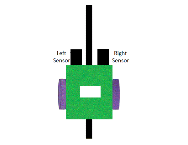
In normal condition, the robot moves in such a way that both the sensors are over white and the black line is amidst the both sensors.
It is programmed to rotate both the motors such that the bot moves in forward direction.
Quite naturally, as time elapses one of the two sensors comes over the black line.
If left sensor comes over the line, left motors are brought to rest and as a result bot begins turning towards left unless the left sensor comes back on white surface and normal condition is achieved.
Similarly, when right sensor comes over black line, right motors are stopped and consequently bot now turns towards right unless the sensor comes back over white surface. This mechanism of turning is known as differential drive mechanism.
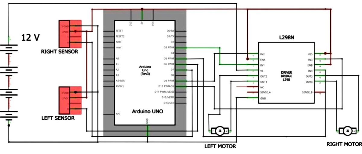
CIRCUIT DIAGRAM:
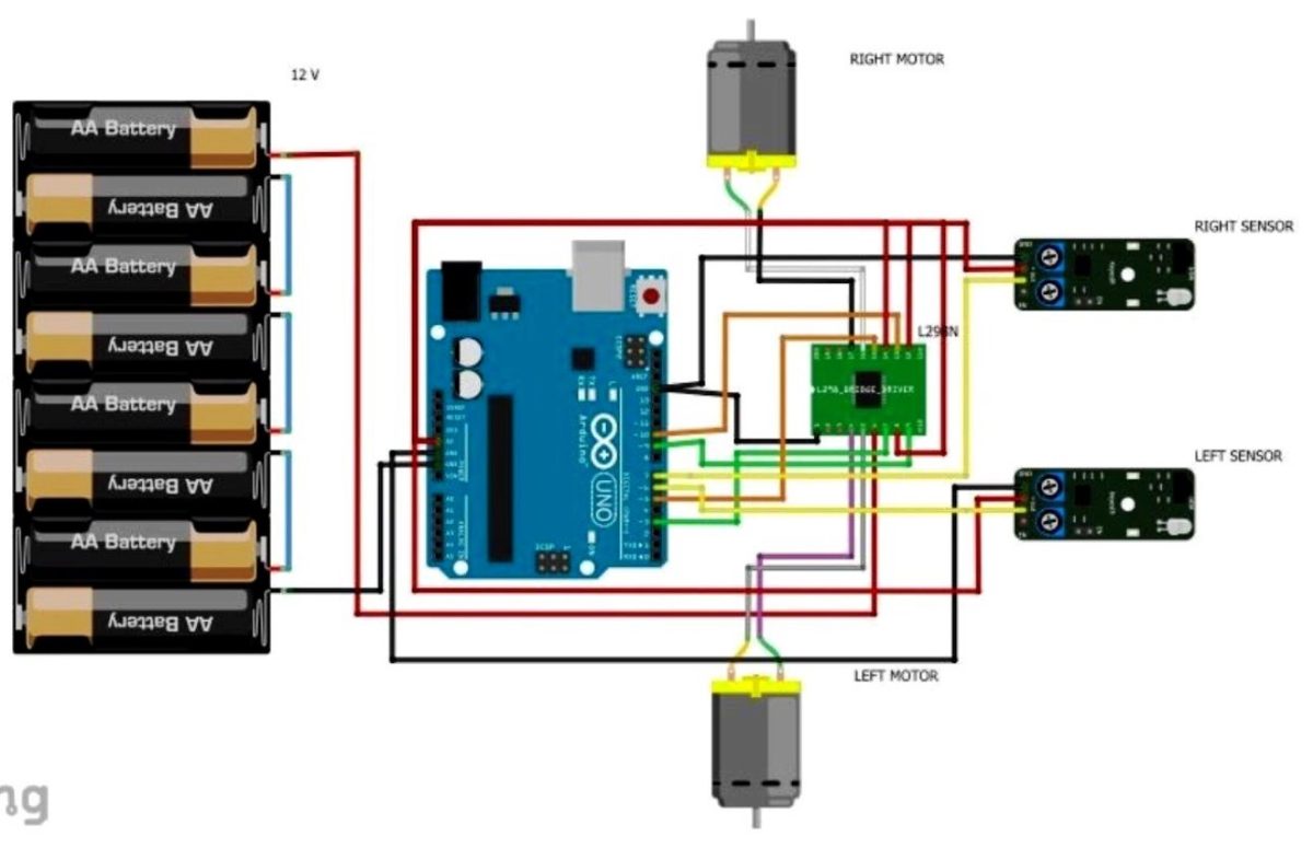
WIRING DETAILS:
PROGRAMMING AND CONCEPTS:
Having done with the circuit part, we will now move on to the programming part . In this section, we will understand the program that controls our robot. Here is the code:/*Created and tested by Navneet Singh Sajwan
*Based on digital output of two sensors
*Speed control added
*/
int left, right;
int value=250;
void setup()
{
pinMode(6,INPUT);//left sensor
pinMode(7,INPUT);//right sensor
pinMode(9,OUTPUT);//left motor
pinMode(3,OUTPUT);//left motor
pinMode(10,OUTPUT);//right motor
pinMode(5,OUTPUT);//right motor
// Serial.begin(9600);
}
void read_sensors()
{
left=digitalRead(6);
right= digitalRead(7);
}
void move_forward()
{
analogWrite(9,value);//3,9 for left motor
digitalWrite(3,LOW);
analogWrite(10,value);//10,5 for right motor
digitalWrite(5,LOW);
}
void turn_left()
{
digitalWrite(9,LOW);//9,3 for left motor
digitalWrite(3,LOW);
analogWrite(10,value);//10,5 for right motor
digitalWrite(5,LOW);
}
void turn_right()
{
analogWrite(9,value);// 9,3 for left motor
digitalWrite(3,LOW);
digitalWrite(10,LOW);// 10,5 for right motor
digitalWrite(5,LOW);
}
void halt()
{
digitalWrite(9,LOW);// 9,3 for left motor
digitalWrite(3,LOW);
digitalWrite(10,LOW);// 10,5 for right motor
digitalWrite(5,LOW);
}
void print_readings()
{
Serial.print(" leftsensor");
Serial.print("\t");
Serial.print(left);
Serial.print("rightsensor");
Serial.print("\t");
Serial.print(right);
Serial.println();
}
void loop()
{
read_sensors();
while((left==0)&&(right==1)) // left sensor is over black line
{
turn_left();
read_sensors();
print_readings();
}
while((left==1)&&(right==0)) // right sensor is over black line
{
turn_right();
read_sensors();
print_readings();
}
while((left==0)&&(right==0)) // both sensors over the back line
{
halt();
read_sensors();
print_readings();
}
while((left==1)&&(right==1))// no sensor over black line
{
move_forward();
read_sensors();
print_readings();
}
}
Description of functions used:
read_sensors(): It takes the readings of both the sensors and stores them in the variables left and right.
move_forward(): When the arduino executes this function , both the motors move in the forward direction.
turn_left():Left motor stops. Bot turns left.
turn_right():Right motor stops. Bot turns right.
halt():Bot stops.
print_readings():Displays readings of the sensors on serial monitor. For this you have to uncomment “Serial.begin(9600)” in void setup.
SENSOR READINGS:
| SENSOR OVER LINE | SENSOR READINGS | |
| LEFT | RIGHT | |
| LEFT SENSOR | 0 | 1 |
| RIGHT SENSOR | 1 | 0 |
| NONE | 1 | 1 |
| BOTH | 0 | 0 |
SPEED CONTROL:
Sometimes the speed of the motors is so high that before arduino interprets the sensor signals, robot loses the line. In short , bot does not follow line due to high speed and keeps losing the line even though the algorithm is correct.
To avoid such circumstances, we decrease the speed of bot using PWM technique. In the code above there is a variable named value.
Just decrease the numerical value in the function to decrease speed. In Arduino UNO you can have pwm values between 0 and 255 only.
analogWrite(pin, value)
0 < = value <=255
This the end of my post on line follower. I hope it is detailed enough to answer all your burning queries and if in the rarest reality it is not, then we always have the comment section available for you. Comment your doubts out. Have a happy tinkering!