Linear Hall-effect ICs are magnetic sensor devices designed to respond to magnetic fields to produce a proportionate amount of electrical output.
It thus becomes useful for measuring the strength of magnetic fields, and in applications that require an output switched through magnetic triggers.
The modern hall effect ICs are designed with immunity to most mechanical stressful conditions such as vibrations, jerks, shocks and also against moisture and other atmospheric pollutions.
These devices are also immune to ambient temperature variations which otherwise could make these components vulnerable to heat producing incorrect output results.
Typically, modern linear Hall Effect ICs can work optimally over a temperature range of -40 to +150 degree Celsius.
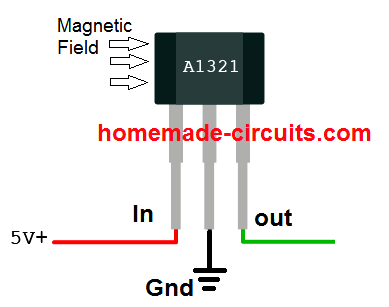
Basic Pinout Diagram
Ratiometric Specified Functioning
Many standard linear Hall-effect ICs such as A3515/16 series from Allegro or DRV5055 from ti.com are “ratiometric” by nature, wherein the devices quiescent output voltage and sensitivity vary in accordance with the supply voltage and ambient temperature.
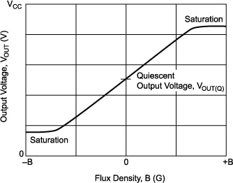
The quiescent voltage could be typically half the supply voltage. As an example if we consider the supply voltage to the device to be 5V, in the absence of a magnetic field its quiescent output would normally be 2.5V and would vary at a rate of 5mV per Gauss.
In case the supply voltage was to increase to 5.5V, the quiescent voltage would also correspond to 2.75V, with the sensitivity reaching the 5.5mV/gauss.

What is Dynamic Offset
Linear Hall-effect ICs such as the A3515/16 BiCMOS incorporate a proprietary dynamic offset cancellation system with the help of an in-built high frequency pulse so tat the residual offset voltage of the Hall material is controlled appropriately.
The residual offset could arise normally due to over-molding of the device, temperature discrepancies or due to other relevant stressful situations.
The above feature renders these linear devices with a significantly stable quiescent output voltage, well immune to all types of external negative impacts on the device.
Using a Linear Hall-effect IC
The Hall-effect IC may be connected with the help of the given connections, where the supply pins must go to the respective DC voltage terminals (regulated).The output terminals may be connected to an appropriately calibrated voltmeter having a sensitivity matching the Hall output range.
Connecting a 0.1uF bypass capacitor directly across the ICs supply pins is recommended in order to safeguard the device from externally induced electrical noise or stray frequencies.
After powering up, the device may require a few minutes of stabilization period during which it must not be operated with a magnetic field.
Once the device gets internally temperature-stabilized, it may be brought under the influence of a external magnetic field.
The voltmeter should immediately register a deflection corresponding to the strength of the magnetic field.
Identifying Flux Density
For identifying the flux density of the magnetic field, the devices output voltage may be plotted and located over the Y-axis of a calibration curve, the intersection of the output level with the calibration curve would confirm the corresponding flux density on the X-axis curve.
Linear Hall Effect Application Areas
- Linear Hall-effect Devices could have diverse application areas, a few of them are presented below:
- Non-Contact Current sensing meters for sensing current externally passing through a conductor.
- Power sensing meter, identical to the above (watt-hour metering) Current trip-point detection, where an external circuitry is integrated with a current sensing stage for monitoring and tripping a specified over current limit.
- Strain gauge meters, where the strain factor is magnetically coupled with the Hall sensor for providing the intended outputs.
- Biased (magnetically) sensing applications Ferrous metal detectors, where the Hall effect device is configured to detect the ferrous material through relative magnetic induction strength detection Proximity sensing, same as the above application, the proximity is sensed by approximating the relative magnetic strength over the Hall device.
- Joy-stick with intermediate position sensing Liquid-level sensing, another relevant sensing application of the Hall device. Other similar application which involve magnetic field strength as the main medium along with the Hall effect device are: Temperature/pressure/vacuum sensing(with bellows assembly) Throttle or air valve position sensing Non-contact potentiometers.
Circuit Diagram using Hall Effect Sensor
The hall effect sensor explained above can be quickly configured through a few external parts for converting magnetic field into electrical toggling pulses for controlling a load. The simple circuit diagram can be seen below:
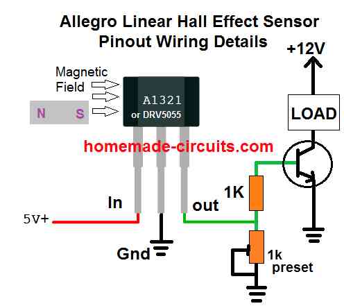
In this configuration, the hall effect sensor will convert a magnetic field within a specified proximity and will convert it into a linear analogue signal across its "out" pin.
This analogue signal can be easily used for driving a load or for feeding any desired switching circuit.
How to Increase Sensitivity
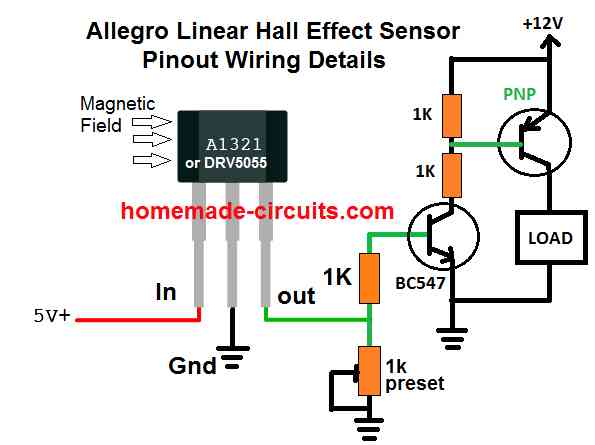
The sensitivity of the above basic hall effect circuit could be increased by adding an additional PNP transistor, with the existing NPN, as shown below:
Using Opamp
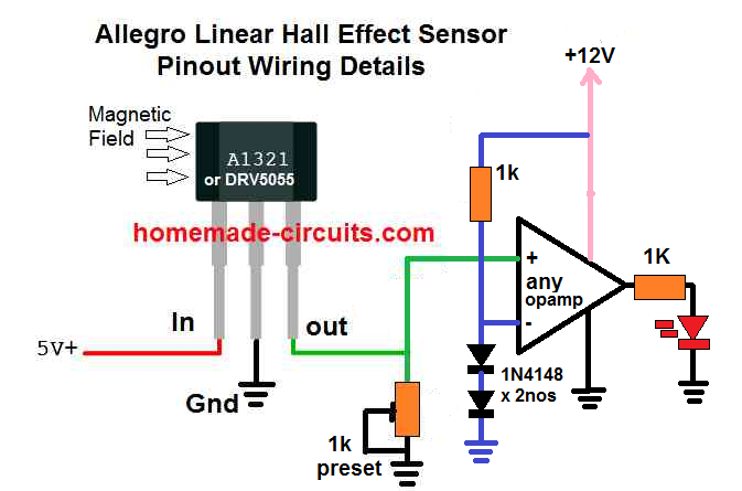
The DRV5055 hall effect sensor can be also integrated with an operational amplifier for getting the switch ON results in response to a magnetic proximity with the hall effect device.
Here the inverting input of the op amp is set to fixed reference of 1.2 V using two series 1N4148 diodes, while the non-inverting input of the op amp is configured with the output of the hall effect for the intended detection.
The 1k preset is used for setting up the switching threshold at which the op amp is supposed to switch, depending on the strength and the proximity level of the magnetic filed around the hall effect.
In the absence of a magnetic field, the hall effect sensor output remains below the set threshold of the op amp inputs.
As soon as the output from the hall effect goes above the non-inverting threshold of the op amp, as set by the preset and the reference level of the inverting input, the output of the op amp turn high, causing the LED to switch ON. The LED could be replaced by another circuit stage for a switching ON some other desired load.


With over 50,000 comments answered so far, this is the only electronics website dedicated to solving all your circuit-related problems. If you’re stuck on a circuit, please leave your question in the comment box, and I will try to solve it ASAP!