In this post I have explained a relatively easy lipo battery balance charger circuit which is designed to continuously scan and charge the connected cells of the battery.
The idea was requested by Mr. Schindler and Mr. Emil Jan Thomas Baticulon.
Charging 6 Li-Po Packs
The concepts are very well written, concise and clear. Thank you so much for the deep coverage of the charging subject.
Have you encountered the need to charge several identical lipo packs regularly? I have that very need, it is time consuming to recharge 6 high power packs containing 4 cells each every few days.
I propose a single cell charger that scans all cells via the balance plugs and serves up the requirement per need during a partitioned interval of the scan period.
Arduino sketch, shift registers, discrete coupling and a plan to stitch it together... there is where I bid you to guide me to a viable implementation. If you'd be so kind?
Charging 18650 Li-Ion Pack
Good day,
I just recently found your blog and upon further reading your post it's very helpful with or without electronic background and i appreciate your work.
I have a project in mind but I am stuck with it, My idea was how can I charge 13pcs 18650 li-on battery in series connection with balancing charger?. Can you help me with it and add this to your work?
Thank you,
The Design and Working
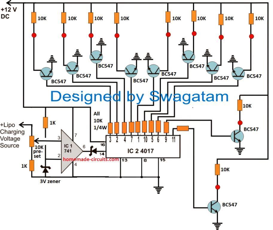
As shown in the following diagram, the proposed Lipo battery balance charger circuit can be implemented rather effortlessly using a couple of IC stages.
Let's try to understand how the circuit is intended to function:
- You can see two DC supply sources in the circuit. One is a fixed 12V for the ICs and the relay driver stages, second is the 4.2V for charging the Lipo cells through the relay contacts. (Make sure to connect the grounds or the negatives of both the supplies together in common)
- This 4.2V is also fed to the non-inverting pin#3 of the op amp via the preset.
- Referring to the circuit diagram below, when power is switched ON, a HIGH signal from one of the IC 4017 outputs randomly switches ON one of the relays through the connected BC547 driver.
- The relay contacts connects the 4.2 V to the relevant Lipo cell. If the cell is discharged it causes the 4.2 V to instantly drop to its discharged level, which may be anywhere from 3 V to 3.9 V.
- This drop causes the op amp pin#3 potential to drop below its pin#2 potential.
- Due to this, the output of the op amp goes low, which does not have any effect on pin#14 of the IC 4017.
- This situation allows the connected Lipo cell to start charging, and as a soon as it reaches the 4.2 V mark, as per the setting of the preset, pin#3 potential goes higher than pin#2 potential.
- This instantly turns the output of the op amp high, toggling pin#14 of the IC 4017 with a clock pulse.
- The above action causes the existing output pin HIGH from the IC 4017 to shift to its next pinout.
- This HIGH causes the next relevant BC547 relay stage to switch ON and connect the next Lipo cell in the same way as explained above.
- The cycle keeps repeating for all the 10 cells, until all the cells charged sequentially.
Control Circuit Diagram

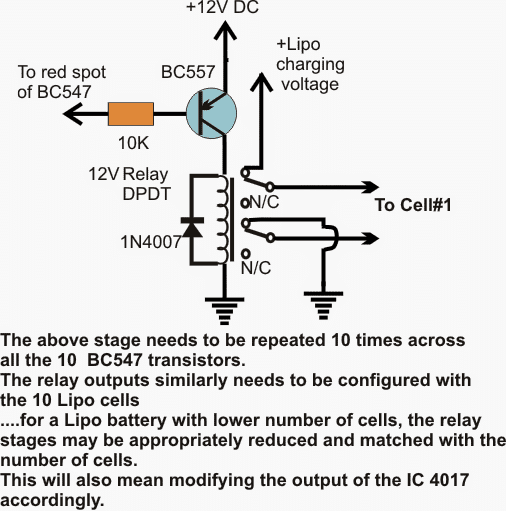
The second diagram below is the relay driver stage which needs to be repeated 10 times and the base of the BC557 associated with the red spots of the relevant BC547 stages from the first circuit below.
Relay Driver Schematic

If the cells are 3.7V rated, the opamp preset is adjusted such that its output pin#6 just goes high when the charge level across the cell reaches around 4.2V.
How to Set up the Balance Charger Circuit
For setting this up, a sample 4.2V may be fed at the shown preset's upper lead, and the preset slider adjusted to make pin#6 of the opamp just high (positive).
- With all the positions connected as depicted in the diagrams and power switched ON, let's assume that at the onset pin#3 of the IC4017 is high which in turns activates the associated BC547, BC557 and the connected relay contacts.
- Cell#1 now begins charging, which drags down the supply voltage across the preset pin#3 of the opamp to may be say 3.4V or whatever may be the initial discharge level of the cell#1.
- While this happens, pin#3 of the opamp experiences a lower potential than it's pin#2 ensuring a low signal at its pin#6 and the pin#14 of the IC 4017.
- As cell#1 of the lipo battery charges, the terminal voltage of this cell slowly increases until it reaches the stipulated 4.2V mark.
- As soon as this happens, pin#3 of the opamp also is subjected at this voltage forcing its output pin#6 to go high, which in turn prompts the IC4017 to shift its pin#3 logic high to it next pin#2, toggling the driver stage of this pin into action.
- The above shift activates the charging of the second cell of the lipo battery in the same manner as it did for the first cell.
- The process now continues and repeats itself by scanning and charging the cells in steps continuously.
- Thus the lipo battery cells are maintained with optimal charging level through the above explained lipo battery balance charger circuit as long as the circuit remains connected with the lipo cells.
Question from Avid Reader Mr. Prithviraj
I am an avid follower of your website www.homemade-circuits.com. Your circuits are always working and awesome for a hobbyist like me to learn and try. I need a small guidance on a question I have regarding LiPo Battery pack.
I am trying to make an e-Bike on my own. I'm building a 24V 6S 18Amp Lithium Ion battery pack which will contain a BMS board for balance charging. My question is, if I try to charge this battery pack directly with a 24V 10A SMPS will that be safe?
I mean, since I already have a BMS built into the battery pack, can I directly connect the SMPS output to the battery pack input/output lines? I am using a 20A 6S BMS in the battery pack. So, also please advise if the 10Amp charger taking is safe too. I will be really grateful if you could please advise.
My Reply:
Yes, you can use the 24V SMPS for charging the mentioned battery. The battery will be safely charged since a BMS is already present in the system.