In this post I have explained a circuit which can be used for monitoring or controlling AC 220V load current by sensing the load current through a contactless current transformer.
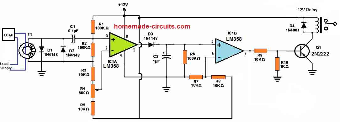
Figure 1 below depicts a circuit diagram designed for a non contact load current sensing through a current transformer, which seemed to work well. It is intended to run on a basic +12 volt regulated or unregulated power source, such as a "wall wart" adapter.
Basic Working Theory
One of the wires of the load is passed through the current transformer. The current through the load wire is magnetically induced into the secondary winding of the current transformer.
This induced current is stepped up by the current transformer and is sent to op amp amplifier stages where it is amplified to finally operate a relay.
The relay switches OFF the load when the current exceeds the cut off threshold, as set by the op amp.

What is a Current Transformer
T1 denotes the current transformer, whose toroid core was salvaged from an old computer power supply.
A current transformer or a CT basically consists of secondary winding having many number of turns whose ends are configured with an external amplifier.

The primary side is created simply by allowing one of the wires of the load power supply to pass through the sensing transformer core.
The current passing through the load supply wire is induced into the secondary winding of the sensing transformer, which is proportionately stepped up by the secondary winding and supplied to the external amplifier for further amplification and detection.
The amplifier circuit amplifies the signal to operate a relay or a switching device for executing the necessary corrections.
Just like any other transformer, a current transformer primary and secondary voltages can be calculated using the following basic formula:
Es/Ep = Ns/Np
where,
- Es = Secondary Voltage,
- Ep = Primary Voltage,
- Ns = Number of secondary turns,
- Np = Number of Primary turns
How turns ratio can be calculated for a current transformer? It can be calculated using the following formula.
Ip / Is = Ns / Np
where, Ip is the current in the primary, Is is the current in the secondary, Np is the number of primary turns, Ns is the number of secondary turns.
In our current sensing transformer, the secondary is made up of about 100 turns of 22 gauge super enameled magnet wire.
The primary is formed by passing the hot side of the load line through the core. This implies that instead of a core suitable to radio frequencies, you should use a core which can tolerate lower frequencies.
The ferrite core selected for this project wasn't ideally suitable; it was probably built for a 20 kHz switching supply, but it still functioned perfectly.
Because the core soon saturates, the output waveform is a very pointed-looking, instead of a smooth sine wave.
How the Circuit Works
To safeguard the opamp, D1 and D2 clip the output waveform, which is capacitively associated to the op-amp input via C1.
R1 and R2 are positioned to bias the non-inverting input to half the supply voltage, while R3 and R5 work similarly for the inverting input.
A comparator is formed using IC 1 a. Its output is rectified through the diode D3 and smoothed using the capacitor C2 and R6, which generate a time constant to ensure that the circuit is neither activated or impacted in any way due to voltage spikes or an unusual waveform from a controlling load.
This alternating current voltage activates second comparator, which powers the output transistor, Q1.
D4 safeguards Q1 from reverse voltage spikes emanating from the relay coil, while the transistor Q1 works like a switch to toggle on the relay.
R4 was introduced so that the circuit could be fine-tuned to meet modest low current loads.
If you want to utilize the circuit with heavy loads (cutting tools, for example), you may omit R4 and just hook the junction of R3 and R5 to pin 2 of IC1a.
R4 is set such that the output of IC1 a is close to zero volts when the control load is switched off and the relay switches in reliably when the load is turned on.
When an oscilloscope is hooked up to IC1a pin 1, and R4 set to the center of the range, it generated a waveform, which ensured that when the load was switched off, pin 1 potential returned to zero.
R9 and R10 serve in lowering the low-level saturated output voltage of U1b, preventing Q1 from turning on at that moment.
You may come across some opamps that simply won't drop low enough to complete the job on their own.
The relay used in this circuit must be rated at 12 V. For switching heavier loads, you may want this relay to be a bigger relay (often referred to as a contactor).
Enclose the circuit, particularly the 120 VAC mains components, in a safe, grounded metal box.
Fixing the box to the metal frame of your table saw could most likely fulfill the purpose.
For operating a heavy load like the table saw, a line cable may be more suitable with an outlet in the box, similar to a single-outlet extension cord, with the black hot wire passing through the torroid prior to getting firmly attached to the hot side (brass color) of the receptacle.
Everything can be protected and contained in this manner. In this case, the simplest method to handle the power supply is to create one from the beginning so that it could be contained inside the enclosure.
A wall-wart power supply option might not be a good idea, since this might end up tumbling out of its socket due to saw vibration or causing a trip hazard if connected into an external socket.
Another Current Monitor Circuit
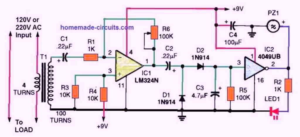
A 220 V AC current-monitoring circuit with an audible and visual warning output is depicted in the figure above.
The difference in the output voltage of the transformer may be balanced out by adjusting the gain of the op-amp using R6.
The circuit can monitor AC current levels between less than 1 amp and more than 5 amps.
In this variable-gain voltage amplifier circuit, one op-amp from an LM324N quad opamp package is connected.
The gain can range from zero to roughly one hundred. The output of the amplifier is coupled with a DC rectifier circuit composed of D1, D2, C2, and C3.
One of the six buffers in a 4049UB IC is linked to the input of the positive DC output signal.
A constant AC output voltage is provided at the secondary of the current transformer by current flowing in the primary, and a positive voltage is supplied at the input of the 4049UB buffer.
Because the IC buffer is an inverter, the output is low when the input is positive. Therefore, neither the LED nor the piezo buzzer are turned on.
The input of the inverter IC becomes low when the load circuit fails to maintain current flow, allowing the positive voltage across C3 to discharge via R5 to almost ground level.
The LED is lit and the alarm is activated as the 4049UB's output increases from a low to a high level.
When the load current is at its lowest feasible level, the gain of the op-amp must be adjusted to provide a minimum of 7 volts DC at the input (pin #3) of the 4049UB.
By doing this, the alarm won't sound when the load is using its minimum amount of current.
How to Build the Current Transformer
The current transformer for the above circuit is a simple design as shown in the following schematic:
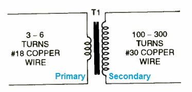
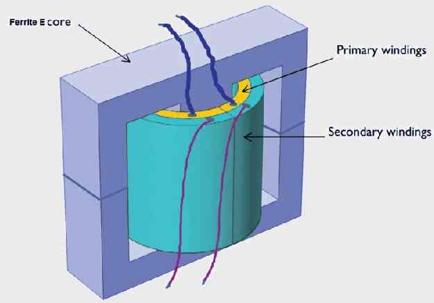
We wind the two winding over a plastic bobbin.
We then insert and place the bobbin in the middle leg of the two E-cores.
We use 6 turns of 18 SWG super enameled copper wire for the current sensing winding which is wired in series with the 220V or 120 V AC load. This forms the primary winding of the current transformer.
We use upto 100 turns of 30 SWG enameled copper wire for the secondary winding which is connected with the op amp circuit.
The number of secondary turns required is determined by the primary side current and the output voltage needed by the monitoring alarm circuit.
About 300 secondary turns are needed for low current levels lower than 1 amp to about 3 amps, while fewer turns are needed for higher current levels.
Hi dear Swagatham,
How can i replace relay with readly available ssr(solid state relay).do need any modification?
Dear Sison,
I have replied to you in your previous comment.
You can replace the relay coil with your SSR input terminals. No further modifications are required.
Thank you Swagatam,
For your express reply.anyway i will try with ssr.same one available in market so expensive.Hope we can switch rapidly with Ssr.
No problem Dr.Sison, Let me know if you have any further doubts or queries.
How can i replace relay with SSR?Any modification required?
You can replace the relay coil with your SSR input terminals. No further modifications are required.
Thank you sir
Hi,
me again, is your DIY CT (T1) can handle up to 15 ampere current – 220 volt? if not, could you pls inform how many turn for secondary winding & what gauge to use, tq in advance
Hi,
For handling 15 amp the primary side wide of T1 only needs to be upgraded accordingly. I think the copper core of the wire can be 2mm thick in order to handle this current safely.
The number of turns can be calculated using the formulas explained in the article.
Hi,
for the first circuit, can I use it for 220 VAC ?
tq
Hi, yes, you can use 220V with a 220V load…
Hi Swagatam
Thanks’ for your useful project. I used 5A:5ma CT for the first circuit and with some modification it works well.
First ,a resistor ( I used 1k) parallel to to D1 is required to avoid core saturation for small loads. Otherwise even for small loads D1 and D2 conduct ,therefor pot R4 become useless.
Second, in order to filter first three cycle (more delay),I add 10k resistor in series with D3 and increase R6 to 330K.
Dear Swagatam ,I was unable to simulate the circuit with proteus nor OrCAD, because there was no model for CT with core saturation(linear transformers won’t work). Do you have any idea how to simulate the circuit to get the desired result?
Thanks so much Dear Emad,
I greatly appreciate your valuable feedback, I hope the users will find it very useful.
Sorry, unfortunately I do not use softwares to simulate my circuits so i do not have much idea regarding the proteus simulation.
By the way, could you kindly send a short video of your working prototype.
I am not forcing you, just a request. If it is not possible then no problem.
I NEED IR2104 SMD.
IN KOLKATA IT IS NOT AVELABLE.
I NEED YOUR HELP TO FIND THE SPARE.
MOB NO 9477651960
WHATSAPP 9831068884
You can try different online sources. There are plenty of online sources available which you can try.
swagatham sir i want 48v dc 20amp buck converter ckt diagram. for e bike modification .
Sreenivasulu, you can try the following design:
https://www.homemade-circuits.com/5v-pwm-solar-battery-charger-circuit/
It is a 10 amp version, first try this, if you succeed with it, then you can upgrade it to 20 amp.
Dear Swagatham,
That was brilliant. 6.8K resistor worked.
Earlier I had tried 2.2K (before I found the fault). Since it didn’t work, I went back to 1K.
Thanks again.
That’s great Suresh, Glad the solution worked. Thanks for updating the info!
Dear Swagatham,
This particular Circuit looks very promising. In fact I can assemble this and connect to the output of the ups, If only a proper pcb is available. What is the maximum current it can sense? response time (or what controls it ?). I recently found even a reputed companies MCB is not fast enough. 8 mosefets got burned along with 2 resistors and one optocoupler and the microprocessor itself because of overload (microprocessor might be my mistake).
[ my hunch is the tracks could not withstand the current load and they burned first and mosfets followed, but none(makers, sellers) would acknowledge this]
This type of circuit could be game changer if its response time is good enough.
Dear Suresh, yes the above project looks interesting, however it was not designed by me, it was contributed through an external source. I do not have the exact detailed specifications of the coil, but I believe the CT and the op amp circuit are highly customizable and the results could be adjusted as per desired specifications. However I don’t think the above circuit can be used as an MCB due to the involvement of an ordinary relay. An ordinary relay can be prone to arcing and the fusing of the contacts.
Dear swagatham,
I have bought all the components. Shall test it and comeback.
That’s great Suresh, I hope you are able to succeed with the project.
Dear Swagatham,
I assembled the circuit. It doesn’t work as expected. This may require several modifications.
I used a 20AMP ct readily available in the market. I think its winding ratio is slightly different , could be 1200:1
If we set the preset so that the output at pin 1 is almost zero, the max we get is about additional 1 volt when load is connected. and the output at pin 7 may vary upto 2 volt. However the voltage at the base of 2n2222 doesn’t vary much to trigger it. I tried the value of R9 as low as 100ohms. The difference between various loads (25 watt soldering Vs 750Watts electric drilling machine ) hardly changes at the base of 2N2222. Any ideas ?
Dear Suresh, the idea was contributed by an external author and the person has referred the circuit from a one of reputed electronic magazines, and this design was tested successfully by the original author, so i am not sure why it didn’t work for you. Did you adjust the preset correctly, or remove it as explained in the article?
Dear Swagatham,
Yes, I tried. What is the voltage required at the base of 2N2222 to trigger it ?
OK thanks Suresh, any normal NPN like 2N2222 will require just 0.6 V across its base emitter to switch ON
Dear Swagatham, This was my understanding too. But got confused when it did not work inspite of getting that voltage.
So I sat with it again and found one open contact. I was using zero board. May be my age is getting better off me. Couldn’t make out the minute gap between the connection. Any way it worked.
Will require some tweeking. working on it. The collector voltage doesn’t drop enough to fire the relay. It stays around 4-5V even with 1300watts load. But , yes it works. The voltage drops from 12 volt to 4-5 v when load is given.
Shall revert back later. Thanks for the input.
Rgds
OK, thanks Suresh, for updating the results! Glad you could troubleshoot the fault and make it work. I think you can try increasing the value of R10 1K resistor to 4k7 resistor and check the response.
Dear Swagatham,
Nice to see this project. Can you explain a little more about CT transformers.
I made a 5000VA (4000 watts) ups using a local assembled kit (sinewave). It uses a microprocessor to control the unit.
It is supposed to be capable of detecting the load and cutoff when the load exceeds. It also displays the load. It never shows beyond 1200 watts even when the load is almost 12amps 225v * 12 = 2700Watts.
The board came with a CT coil DTCT103C which is said to be 10 amp rating (though I think it is 1000:1). This is a little confusing when one website says it is 10 amps and another tells as 1000:1 . This is very small sized coil. I suspect the inability to display the higher load beyond 1200 watts (aprox 5 amps) is something related to the CT coil used.
Can you throw some insights about this / how I can go about solve this. Will fixing a 30AMP coil fix this issue ?( Should it be in Ratio , instead of amps ???)
Dear Suresh,
As explained in the above article, a CT is supposed to have a high number of secondary turns which is supposed to absorb the current induced magnetically from the load wire passing through the core of the CT. So in your case the 10 amp suggests the maximum current range that can be passed through the load wire through the core of the CT. 10 amps seems to be the maximum current detection range of the CT. However, it ultimately depends on the adjustments of the amplifier circuit which determines the maximum current range that can be detected through the CT.
Lower current range means the CT is more sensitive and vice versa. 1000:1 probably indicates the secondary to primary ratio, meaning if the load wire is a single turn acting like the primary of the CT, then the secondary could have a 1000 turn winding.
Dear Swagatham,
 " alt="current transformer sample 1:1000" />
I found another site that gives a little more details about this particular CT.
It says
Rated input current: 5A
Rated output current: 5 mA
Ratio: 1000: 1
Linear range: 0-10 A (100 Ohm)
Linearity: 0.2%
Insulation voltage: 3000 V
So the maximum it can read is upto 5A which it converts to 5mA.
This may be why the display never shows beyond 1200watts approx 5 amps.
They have another ct rated at 20 A
Winding Ratio 1:1200
Frequency : 50 Hz
Recommended Burden Resistance (Ru) : 120 Ohms @ V out = 0.5 Volts.
Maximum Primary Current (Imax) : 20 Amp.
AC CURRENT MEASUREMENTS ONLY
CAN NOT USE IN DC
See what these sellers do. There is no uniformity in providing details . Every thing is different. How can we be sure of the product we buy ?
This is why I am trying to find more about this. pls chk when you get time.
Thank you Suresh,
You are right, the range says 0 to 10 amps, while the maximum current is given as 5 amps, that’s slightly confusing.
Hi. Please can you help me with 6kVA and 10KVA Single phase voltage & frequency stabilizer circuit?
Sorry, presently I do not have a stabilizer circuit of this scale.
por que você não mostrou o circuito sendo medido por um osciloscópio ?