In this article I have explained a few simple loop based security alarm circuits, categorized under closed loop, parallel loop, and series/parallel loop. All these designs could be customized and used for a variety of security alarm applications.
Overview
In a loop alarm circuit, more than one sensor is used, each one wired with a certain type of detection loop, and inserted across tactical areas, on or around the gadget which is to be guarded.
The detection or the sensor circuit (which involves a sensor loop and trigger circuit) controls a burglar alarm device or siren that, when initialized, generates an loud sound, or a visible warning illumination.
The sensor device in these type of alarm circuits is generally as basic as an individual strand of thin metal wire, which works like a sensor and is placed around the perimeter of the target to be protected. So long as the cable stays undisturbed, the alarm circuit remains in the alert position. In the event an intruder severs the the wire, the sensor turns ON and sends a signal to the trigger circuit, sounding the alarm.
This form of sensor actually comes under the category of one shot non-resetable, system. These security systems necessitate the sensor wire to be changed following each infringement. (These are known as closed-loop circuits.)
On the other hand, the majority of alarm circuits apply certain type of magnetically triggered switch, that can be reset and applied repeatedly, like a sensor. The sensor could be sometimes a normally-open or normally closed magnetically triggered switch. Plus, according to the settings of the trigger arrangement, several sensors could be wired up in series or parallel into the circuit.
Quiet Alarm
The very first circuit, as shown in Fig. 1 is created using 1/2 of a 4001 CMOS quad 2-input NOR gate, put together like a set/reset latch. When the circuit is in the reset condition (standby mode) and switch S1 open, gate U1a's output stays at logic low.
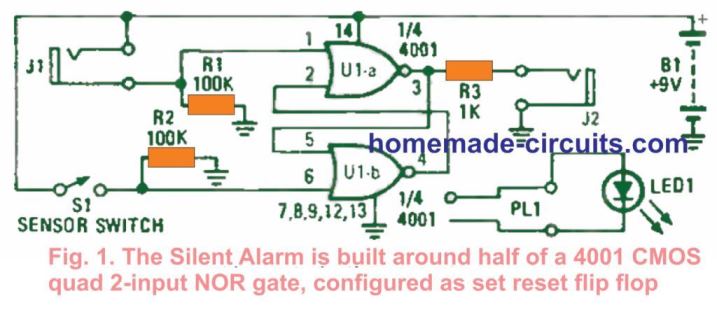

When the key (an LED attached within a mini phone plug, PLI) is connected to jack connector J2, the LED remains shut off, showing that no infringement has happened.
However, as soon as S1 is closed, may be just briefly or entirely the output pin 3 of U1- a goes logic high and continues to be high until the circuit is reset. When the key is inserted into jack connector J2 following an infringement, the LED lights up.
Putting the key into J1 resets back the circuit. In the idle condition, the circuit consumes hardly any current, enabling it to maintain a resolute monitoring for several months reliably. In case the sensor (S1) is set off by an intruder, the circuit records the details in a temporary storage with no additional current draw.
Closed-Loop Alarm Circuit
Our next alarm circuit see Fig. 2, works by using a chain of 3 series-connected normally-closed switches (constituting the closed-loop configuration), wired to an SCR gate.
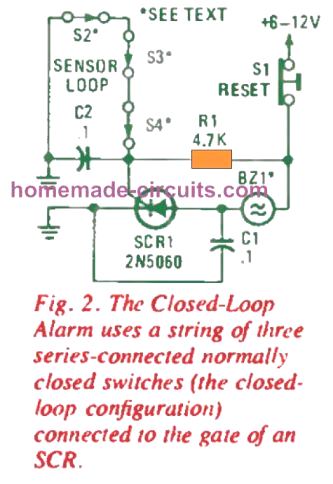

Just about any number of sensors could be attached in series and accustomed to activate the circuit. In the idle condition, the circuit consumes around 2 mA, however the current drain may possibly increase to all the way to 500 mA if the circuit is activated, depending on the attached alarm device specs.
The circuit's functioning is extremely straightforward. Having all sensor switches in the closed position and power switched ON, the potential at the SCR's gate becomes close to zero.
The only current depletion is by means of R1 and the closed sensors. However as soon as any of the sensor switches opens, either briefly or completely, the gate current for the SCR is turned ON via R1.
This activates the SCR, enabling a ground conduction for the alarm horn device, which now begins to wail. Also, the moment this activation happens, the alarm gets latched and continues to sound for so long as the reset switch (S1) stays activated.
Capacitors C1 and C2 are integrated in the design to stop possible voltage spikes from spuriously initiating the SCR.
Parallel-Loop Alarm Circuit
Our next alarm circuit, see Fig. 3, is practically the same as the circuit provided in Fig. 2, with the exception that the sensors are rigged in parallel, which is known as an open loop configuration.
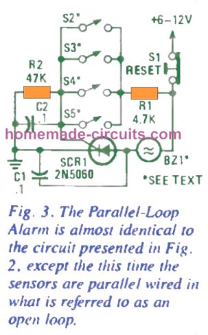
Basically, this schematic makes use of normally-open sensor switches as shown below.
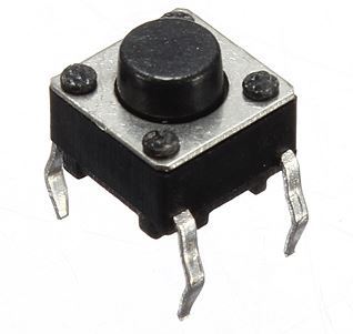
Any desired quantity of normally open switches could be included in parallel and be employed to activate the alarm; these are attached to the SCR as indicated in the schematic.
In the standby mode, the alarm circuit pulls minimal current, which makes it a superb choice as a battery powered unit. However as soon as any of the input sensors is turned ON, gate current moves via R1 to the SCR, switching it on and triggering the alarm horn.
The horn may continue sounding until the circuit is reset or the power supply or battery depletes off completely.
A Simpler Parallel Loop Alarm
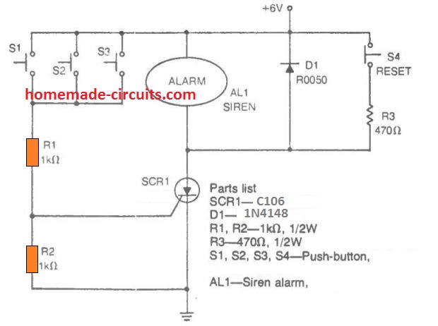
The parallel loop alarm example shown above actually is very much self-explanatory. The switches S1 through S3 are positioned across various strategical positions within a premise which is to be protected against an intruder.
As soon as an intruder walks across any one of these switches and causes it to get depressed or closed, the voltage is allowed to reach the gate of the SCR via the switch and R1. This instantly switches ON the SCR and latches ON the associated alarm siren.
The system is deactivated only by switching off the supply input.
Series/Parallel-Loop Alarm Circuit
The following circuit, as given in Fig. 4, integrates the alarm in Fig 2 with the one in Fig. 3 to feature series- and parallel-loop protection together. In this design you could employ both normally-closed and normally-open sensors to activate the same alarm device.
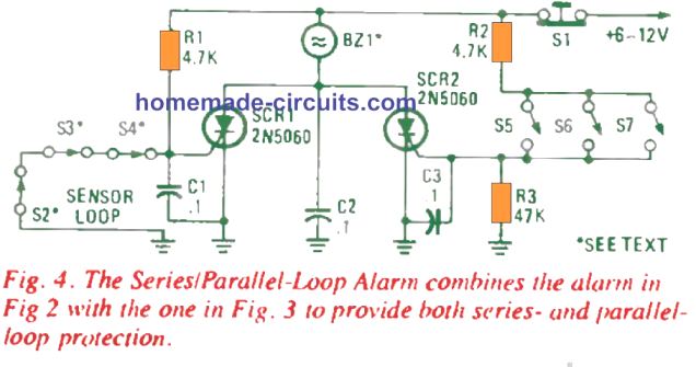
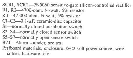
It is important to note that the primary difference between the two sensor loops is identified by the manner in which each sensor switch associates with the others within the loop and also the manner in which each loop is hooked up with the circuit.
The loop linked to SCR1 keeps the SCR switched OFF by clamping its gate pin to ground line via the loop sensors. Opening all of these sensor switches (S2-S4) disconnects the gate ground link, letting the gate current to be applied to SCR1.
This allows the SCR1 to activate and sound the alarm device. In contrast, SCR2's gate is kept to zero potential through R3. When any one of the associated sensor switches (S5-87) are closed, the gate of the SCR gets attached to the positive supply by means of R2, causing it to start up, and turning ON the alarm.
With one of the sensor switches closed, R2 turns into a gate pull-up resistor. The moment it's triggered by any of the sensor loops, the circuit goes on to sound the alarm for so long as the S1 switch is not pushed for the reset actions, which can be seen wired in series with the supply voltage input.
Note that cutting off the trigger supply doesn't have any impact on the SCR conduction, until the current through the SCR is not interrupted. As soon as switch S1 is closed, it causes the current via the SCR's to become minimal, disabling the SCR's. Capacitors C1-C3 stop the circuit from getting spuriously triggered by voltage spikes.
Another Example of Series/Parallel Loop Alarm
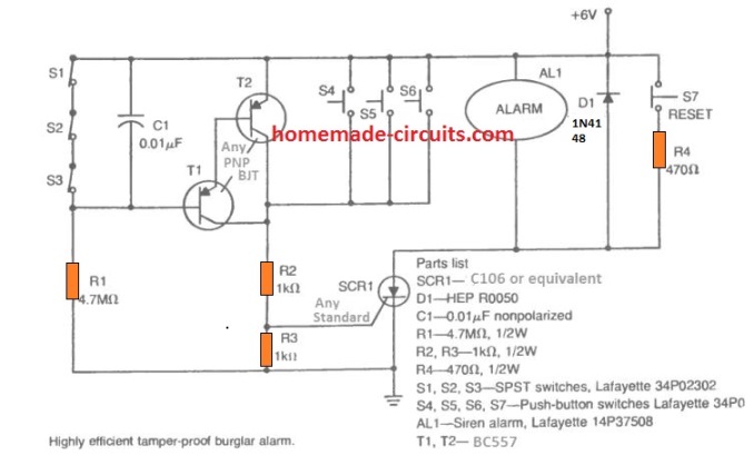
If any of the switches S1---S3 is opened, the T1/T2 gets the base biased through R1 and is activated, which in turn latches ON the SCR, and sounds the alarm ON.
Conversely, if any of the switches across S5---S6 is pressed or closed, the SCR gets the gate triggers via R2 and latches ON along sounding the alarm.
High Power Alarm Driver
All the customized alarm circuits talked about so far were simply designed for low to medium power alarm devices because of the low current specifications of the SCR's connected with these.
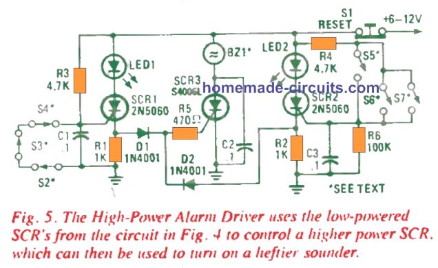
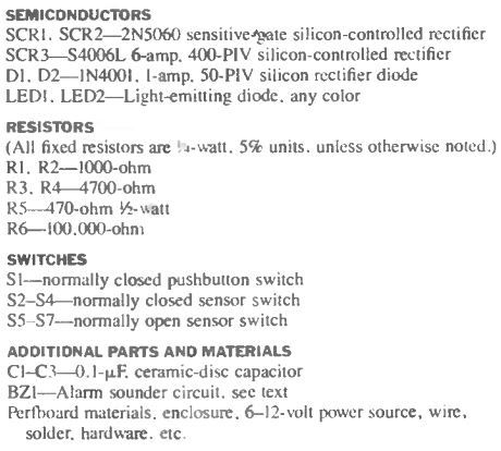
The circuit in Fig. 5 on the other hand, makes use of the SCR driver stages exactly similar to the earlier models, but the SCRs are replaced with higher-power ones, capable of handling much heavier and louder alarm devices.
Both the sensitive-gate SCR's are hooked up in individual sensor/driver circuits. Similar to the circuit in Fig. 4, SCR1 is set off by the normally closed sensor loop (S2-S4), while SCR2 is activated by the normally open sensor loop (S5-S7).
The output (at the cathode) of each SCR we find the gate of a 400-PIV 6- amp SCR (SCR3) connected through a separate driver diode and a common current-limiting resistor, R5.
In case any of the normally closed switches (S2-S4) opens, gate current begins flowing by means of R3, turning ON the SCR1, which lights up the LED1 revealing that a infringement has happened across one of the normally closed sensors.
Simultaneously, the SCR's cathode voltage climbs up to approximately 80% of the supply voltage, resulting in the current to move via D1 and R5 into the SCR3 gate, switching it on and triggering the alarm horn.
SCR2's normally open sensor loop works in exactly the same fashion. As soon as any of the normally open sensor switches (S5-57) is pressed down, SCR2 gets activated, illuminating LED2. Also simultaneously, a gate current is delivered to SCR3, triggering the alarm.
Multi-Loop Alarm Circuit
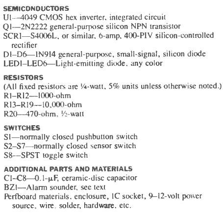
The circuit (Fig. 6) explained next is a multi-input alarm having a LED lamp for indicating the status for each sensor. The trigger circuit works nicely as a status indicator when switch S8 is moved to the MONITOR position.
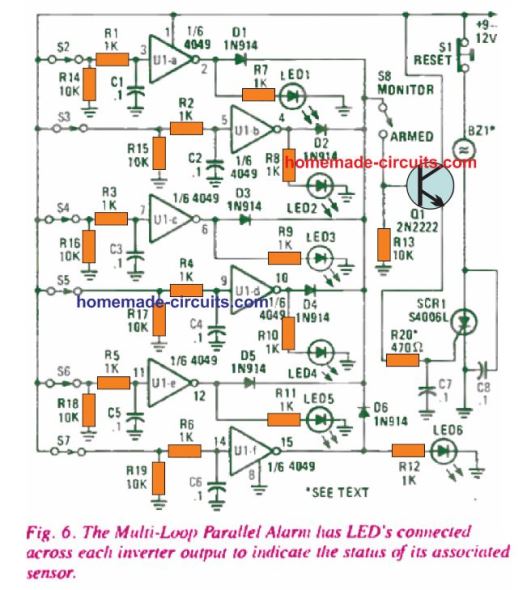
With S8 shifted at the MONITOR position, it allows the sensor circuit to be used throughout job hours to monitor door closing and opening and also other typically vulnerable places which are secured only during the non-working periods.
A 6-amp SCR is employed to enable a high-powered alarm device to be controlled using the system. The circuit's working procedure is very simple.
A 4049 hex inverting buffer is utilized in order to isolate each one of the 6 input sensors. While S2 is in its normally-closed situation, the input of U1-a at pin 3 is hooked up to the positive supply.
The high input results the U1-a's output to stay low. With a low output, LED1 is shut off, with no current entering across the diode D1.
When S2 is opened, it drags the input of U1-a low by means of R14, driving its output to move high, causing in LED1 to illuminate, and in the course applying a bias voltage for Q1 base via D1 and S8.
The acion activates Q1, providing adequate gate current for the SCR1 via R20, so that it triggers ON. This in turn switches ON the alarm horn BZ1.
Each one of the other sensors/ buffers circuits also work in the exact same fashion.
The transistor is wired up in an emitter-follower setup to ensure proper isolation of the buffer outputs and enhance the SCR's gate current so that it turns on optimally.
The circuit can be improved to deliver a series-loop security by replacing a string of sensors (may be 3 or 4) switches for each normally closed switch implemented within the specific loop.
You can furthermore utilize the circuit simply like a status monitor by getting rid of the diodes (D1-D6) as well as the associated circuitry.
Additionally, piezo buzzer could be attached from the diode end of S8 to ground in case an audible output is preferred when the system is used for monitoring purpose only. When many more unique inputs are expected, it shouldn't be difficult at all by employing an additional 4049 hex inverter into the circuit.
Swagatam – thank you for the prompt reply. I think I figured this out. I’m replacing a defective burglar alarm system with a Honeywell Ademco Vista-20P system. The schematic shows several ELOR loops, one loop for each of zones 2 thru 8. The hot side of each loop has several NC sensors (they’re NO held NC by magnets), and has a 2K ELOR resistor across the terminals at the end of the loop.
Then, they show a normally open switch across the 2K resistor. I couldn’t figure out what the reason for the NO switch. Now, I think that could be 1 or a group of NO sensors.
I don’t know if my present (defective) system uses sensors across the 2K resistors: most of my windows and doors have sensors, I’ll get into that next week.
Bob
Thank you Bob, for updating the information.
On the Vista 20 schematic, what is the NO switch in parallel with the EOZ resistor?
What is Vista 20 schematic? I did not understand your question.
Hi Swagatam,
I want to design a circuit to play an edge triggered Melody Chip when a cabinet door is left open after a delay. My cabinets have a door switch that turns on 12v strip LEDs to provide light inside the cabinets. My wife leaves the doors open which uses unnecessary electricity. I have some of the Chinese music chips which are edge triggered. Simple enough to use a 555 timer as a delay so normal opening and closing of the door does not play the music(alarm). The problem is she leaves the door ajar and leaves the area. After a delay the alarm plays once and then is in standby until the door is closed and reopened. How can I retrigger the edge triggered music chip after another short delay and repeat until the door is closed? The music chip uses 3-5v so I have a LM7805 and a couple of diodes inline to reduce the output from the 5v regulator as safety. These chips will burn out pretty easily if the voltages surges. My refrigerator will play a short alarm if the door is left open and will repeat the short alarm every few minutes. I would like to do the same with my cabinet doors. Thanks!
Hi Norman, you can probably use another 555 circuit, this time an astable circuit, and hook up the delay timer with this circuit such that it keeps the timing capacitor of the astable shorted. Once the delay period is over, the short circuit is removed which allows the 555 astable to function normally and produce the intended output ON/OFF oscillations whose timing can be set appropriately.
To convert the ON time into a short pulse, you can add a capacitor in series with the output pin#3 of this astable.