The 220 V mains AC line filter circuit described here has two functions: it prevents high-frequency waves from being sent back into the power network and it protects connected equipment from power line disturbances and surges.
This circuit employs a number of components, such as capacitors, resistors, inductors, and a varistor, which are deliberately positioned to dampen surges, discharge capacitors, and form a low-pass filter to prevent high-frequency signals.

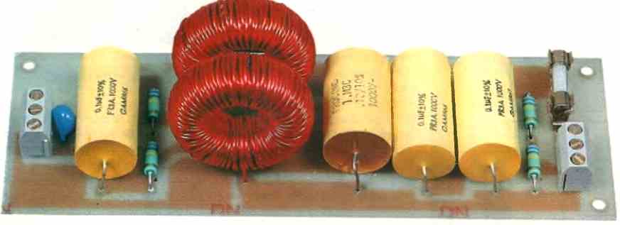
The printed circuit board design and wiring are critical parts of efficiently applying this filter. The circuit may be successfully manufactured to give best performance and protection by following the specified circuit architecture and applying correct replication procedures.
Circuit Description
The circuit diagram of the EMI AC line filter is shown in the following figure.

The AC voltage first encounters a varistor (such as the SO7K250 type), which is responsible for strongly attenuating any instantaneous overvoltages that may be present on the power lines.
Next, there is C1 and a high-value resistor (R1), which serve to discharge the capacitors.
Two inductors (L1 and L2) are then placed in series with each power line and, along with the various capacitors (C1, C2, C3, and C4), they form a low-pass filter designed to block high-frequency waves.
A second resistor (R2) is placed after the inductors and serves the same purpose as R1. A fuse is connected at the output to prevent exceeding the current that the wires used for winding the inductors can handle.
Construction
The layout of the printed circuit board for the 220 V line filter circuit is shown in the figure below.
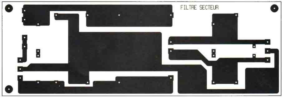
It is important to follow the track layout, and the best method of reproduction in this case would be photocopying onto transparent plastic.
The wiring will be done according to the placement diagram shown in the figure below.
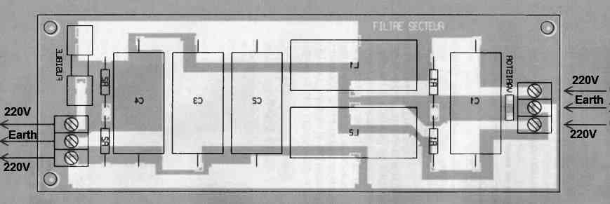
The four capacitors (C1, C2, C3, and C4) will be installed first.
Their operating voltage should be a minimum of 1,000 volts DC to withstand the 220 V AC voltage applied to them.
The printed circuit board allows for the possibility of using either a single resistor or two resistors in series for R1 and R2. These resistors should also be able to handle the supplied voltage.
The two inductors will be toroidal models used for suppressing interference in triac circuits and should be able to handle a minimum current of 2 A.
Their value should be between 100 uH and 300 uH. These inductors are readily available at many electronic retailers.
Once the wiring is completed, it will be necessary to check the solder joints on the printed circuit board to detect any short circuits between adjacent tracks, which could result in a spark when powered on.
The tests can only be performed by connecting the filter equipment between AC 220 V AC input and the desired electronic equipment.
Another Simple Transient Filter for 220V mains AC Supply
Fluctuations in voltage known as transient spikes, which can reach levels of 200V or even higher than the peak voltage of the main power supply, are quite commonplace. Additionally, there exists a significant presence of radio frequency (RF) noise.
Both these factors have the potential to deteriorate the performance of delicate electronic equipment.
Enthusiasts of high-fidelity audio systems are likely familiar with the consequences of these issues.
They can range from easily noticeable and bothersome instances of cracking and popping sounds to more subtle effects such as a pervasive sense that the audio playback isn't achieving the pinnacle of perfection it could.
Likewise, in the realm of computers, few things are as exasperating as experiencing a program crash with no discernible cause or discovering that crucial data has been corrupted.
Why a Mains Line Filter Circuit
The purpose of this 220V AC mains line filter EMI circuit is to tackle these irregularities and offer you a cleaner and comparatively unpolluted power supply.
A voltage-dependent resistor is employed to absorb a significant portion of the energy stemming from transient spikes.
Additionally, a line filter is implemented to eliminate the remaining RF noise. The circuit board (PCB) has a compact footprint, rendering it compatible with the internals of nearly any hi-fi amplifier or tuner.
For setups involving home computers and other equipment constrained by limited space, this filter can be constructed within a compact plastic enclosure.
It is then connected in series with the main power cord, addressing power quality issues effectively.
How the Circuit Works

The Voltage Dependent Resistor (VDR) functions in a manner akin to a bidirectional zener diode.
Initially, it exhibits high resistance until the voltage across it attains the varistor voltage – 430V for the specific component utilized in this project.
Beyond this point, the resistance sharply declines to an exceedingly low level.
As a result, it dissipates the majority of energy from transient spikes and imposes an upper limit on the voltage.
During a brief pulse of a few microseconds, the varistor absorbs significant energy and can even conduct currents of several hundred amps, if necessary.
The inductive aspect of the filter consists of two coils wound in opposing directions on the same core.
Equal currents moving in opposite directions through these coils, as typically found in mains current, result in no net magnetic influence on the core.
However, any imbalanced current due to noise on the line encounters the complete inductance of the coils.
This differential effect is then attenuated by the filter, effectively reducing the noise.
How to Build
The arrangement of components depicted in Figure below serves as the blueprint for constructing this EMI AC line filter circuit.
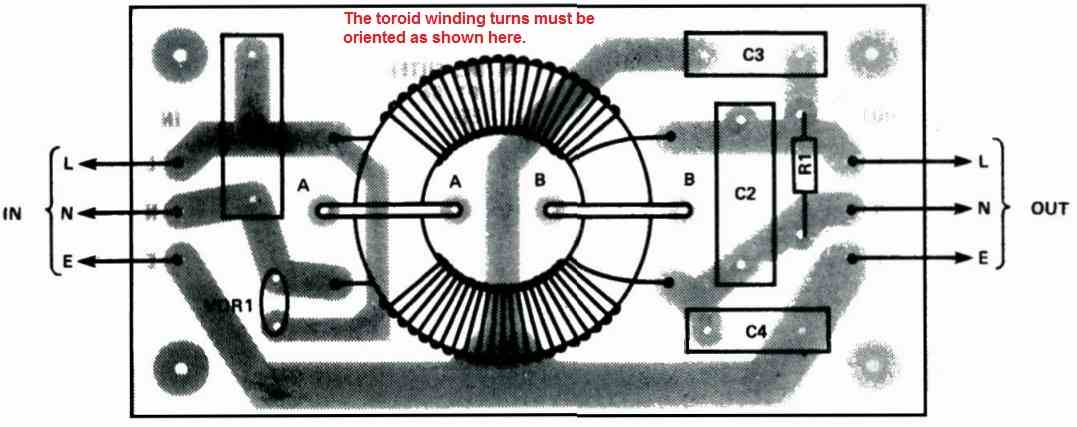
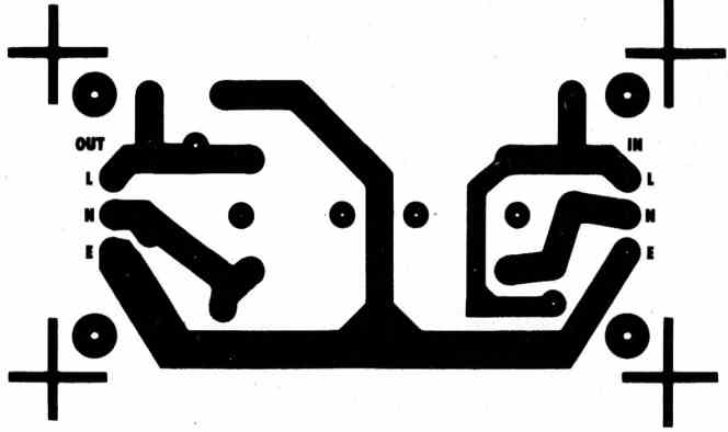
The toroid requires the winding of two coils, each comprising 20 turns of 22SWG enameled copper wire. It's crucial to wind the coils following the orientation illustrated in the diagram; otherwise, the functionality of the filter could be compromised.
When using a toroid coated with nylon, the coils can be directly wound onto it. In the case of an uncoated toroid, an initial layer of insulation is necessary – applying a few coats of polyurethane varnish should suffice.
For temporary placement, the toroid can be secured by twisting its wires together behind the PCB.
Subsequently, firm fixation to the board can be achieved by employing two slender cable ties through the M and BB holes. After ensuring evenly spaced turns of the coils, a final layer of varnish can be applied to the entire assembly.
Finally, the leads should be trimmed and soldered to the PCB.
Most contemporary "enameled" wire features a coating that melts upon contact with a soldering iron, serving as its own flux. Note that the higher melting point might prolong the soldering process.
It's imperative to adhere to the specified capacitor types for this project.
Introducing capacitors across the mains can result in fires and potentially life-threatening electric shocks during fault conditions. For connection between 'live' and 'neutral' points, employ Class X capacitors.
For links to mains earth, opt for Class Y devices. These capacitors are engineered to mitigate catastrophic outcomes even in the event of failure.
The existing circuit design is appropriate for devices drawing up to 5 Amps, restricted by the gauge of wire in the toroid winding.
Should you desire to enhance the rating, the PCB has the capacity to accommodate a larger toroid and heavier gauge wire.
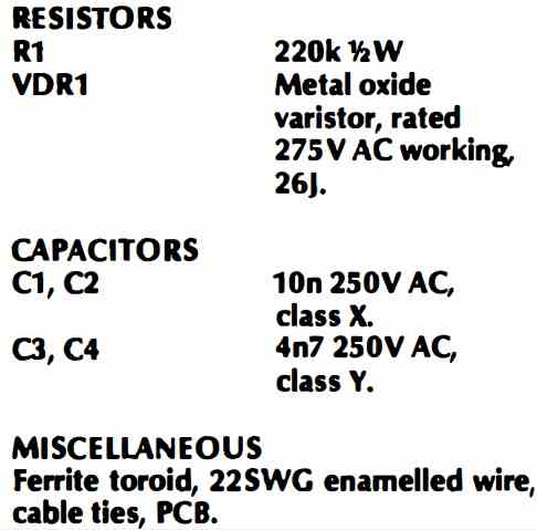
Parts List
The parts list for the above explained mains 220V AC EMI line filter circuit is given below:
Hi. interesting project, but the only thing that concerns me is the value of the phase to earth capacitors (100nF). These two capacitors trigger elcb protectors, and measure half mains potential at the junction. Most of the information I have studied recommend nothing larger than 4700pf. Could you clarify this please?
Hi, if your system includes an ELCB and it gets triggered by this 0.1uF capacitor across phase and earth, in that case you can reduce it to some lower value, otherwise 0.1uF is a good value for an enhanced filtration…
The diagram and the parts list give two different values of parts. I wanted to know the Wattage of the resistors.
All resistors are 1/4 watt 1% MFR, unless specified.
Which part in the parts list is not matching with the diagram?
Hi Swagatam,
Thank you for all the material you have posted.
I’m working on an SMPS design and wanted some of your input for the first section.
The input is residential split phase 240V.
Attached Image.
Your inputs/comments are much appreciated.
Regards
Alan
Thank you Allan,
Your circuit looks good, however the MOV must be ideally situated just after the mains AC input supply and before the fuse.
Let me know your thoughts on this…
You are right. I have updated the schematic.
Regards
Alan
Thanks for the update, now it looks OK to me…
However, instead why not go as per the first diagram in the above article:
" rel="ugc">
Yes. Your circuit incorporates those damping resistors which might be more effective. I was trying to reduce the PCB form factor (still have the switching components and others).
Are you using differential mode inductors initially instead of a common mode?
I am planning on using a PI filter after the rectification. Is there a significant advantage of one over the other?
Please let me know.
In the first design it is a common mode choke configuration. Yes, a PI filter should help to enhance the filtration greatly if you are using it after rectification, along with the common mode inductors.
Hi Swagatam,
It is great what you are doing for the community.
Here are a few more ideas that you can add.
Add GDT in series with the MOV’s, add fuses in series with them.
To increase capacity, and expand the life of the MOV’s, you can use them in parallel. So instead of 1, you can use two of the same type, so in this circuit, it would be two. If you were to add the L-E & N-E, instead of have 3 total MOV’s, you would have 6.
On another note, to prevent ringing in the CM choke, and to protect your downstream circuit, you can add an appropriately sized GDT, as also explained in this Youtube video by Mitsubishi:
https://www.youtube.com/watch?v=C-pV72GzQj4
This is just some ideas for the people that read the comments section.
Regards.
Thank you Aries1470,
I appreciate your valuable feedback, I will add the information directly in my article soon.
it would be best to add two more varistors between hot1 to hot2 and hot2 to earth