In this article I have explained a simple overload cut off circuit for safeguarding heavy mains operated machines such as a lathe machine. The idea was requested by Mr. Howard Dean.
Technical Specifications
May I first say I have very little knowledge of electronics although I could follow a simple diagram.
I operate a small Chinese lathe for hobby machining (making model steam engines) but occasionally the system is overloaded and a 3 amp fuse blows, I appreciate this fuse is there to protect the motor.
Would it be possible to replace this fuse with a cut-out switch rather like a domestic unit so that I don't have to change fuses.
The problem does not occur often but when it does it is a damned nuisance getting to the fuse as it is situated at the back of the lathe which I have to haul around. A bit much at 75.
Any assistance would be appreciated.
Many thanks.
Howard Dean
The Design
I have already discussed one simple overload protector circuit design in one of my previous posts, the same can be utilized for the proposed lathe machine overload cut off application.
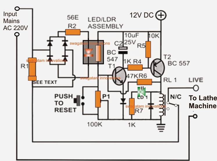
Referring to the circuit diagram below, we can identify the following main stages in it:
An opto coupler stage driven by a bridge rectifier
and a latching relay circuit stage coupled with the above opto coupler stage.
Circuit Diagram

The AC mains is supplied at the indicated left side input, which is passed on to the load via a load sensing resistor R1 and the associated cut off relay's N/C contacts, N/C stands for normally closed, meaning the contacts are connected across this point while the relay is in a deactivated state.
R1 is suitably calculated such that a potential difference sufficient enough to trigger the opto LED develops across it whenever an overload exceeding the unsafe zone is reached.
The overload cut off operation is executed in the following manner:
For so long as the load is within the the normal range of consumption, the voltage across R1 stays low, keeping the opto LED disabled.
However in case of a short circuit or an overload at the output, which may be in a lathe machine for the proposed design, the voltage across R1 shoots and becomes sufficiently high so as to switch ON the opto LED instantly.
The opto LED in turn illuminates the associated LDR sealed inside the light proof enclosure causing its resistance to drop significantly.
This drop in the the LDR voltage allows a biasing current to the base of R1 which along with T2 instantly flips into a latching mode switching ON the relay.
The relay contacts respond to this and deliver the required changeover cutting off the AC line to the load or the lathe machine.
The circuit stays latched and frozen until the power to the circuit is switched OFF and switched ON resetting the relay in its initial form. Alternatively the shown push button may also be pressed for the same.
The green LED indicates the latched mode of the overload protector circuit and also confirms a power off to the output load.
The opto coupler is a homemade device, the construction details may be studied in the following article:
https://www.homemade-circuits.com/2011/12/how-to-build-simple-electronic.html
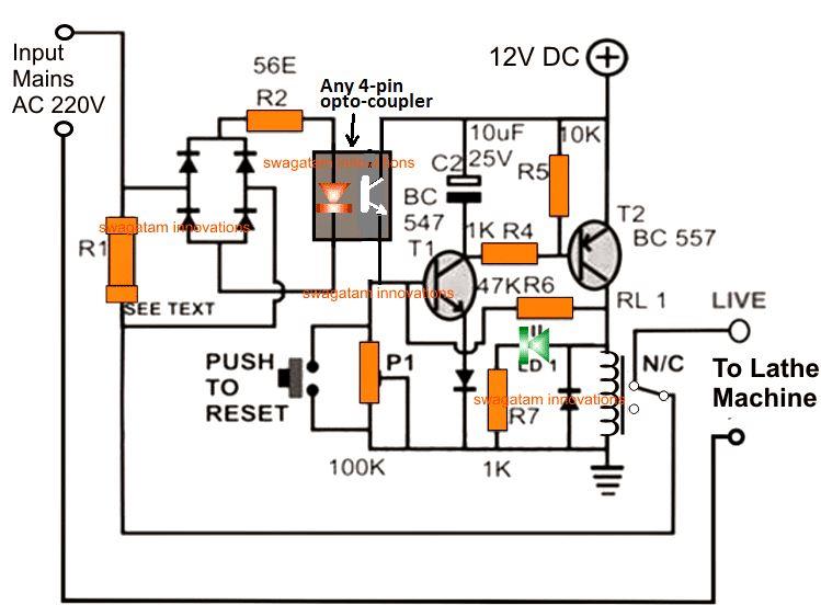
Using an LED/LDR combination for the opto coupler appears to be much reliable in its operations, however a conventional LED/transistor opto (such as a 4n35 etc) can also be tried instead, and might just work as reliably, it could be a matter of some experimentation.
Using an Opto-coupler
The above design can be also built using an opto-coupler instead of an LED/LDR assembly, as shown below:

Current Limit Formula
R1 may be calculated using the following formula:
R1 = LED forward voltage / overload current (in amps)
P1 s for adjusting the sensitivity of the circuit.