The proposed 48 V automatic battery charger circuit will charge any 48 V battery up to an optimal 56 V full charge level, utilizing very ordinary components. The circuit is highly accurate with its over charge cut off features.
Circuit Description:
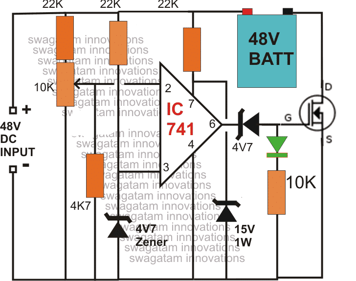
As shown in the circuit diagram, the main element in the circuit is the opamp IC 741, which has been arranged as a comparator.
Pin#3 which is the inverting input of the IC is referenced with a fixed voltage of 4.7V through the respective zener/resistor network.
The other input is applied with the sensing voltage which is actually the voltage merged from the supply and the from the battery, in other words the charging voltage which is applied to the battery for charging.
The resistor network at pin#2 along with the preset forms a voltage divider network which is initially adjusted such that the voltage at this pin stays below the voltage level at pin3, which is the reference voltage set at 4.7v by the zener diode.
The preset is set in such a way that the voltage at pin#2 rises above the 4.7 mark as soon as the battery voltage rises above 50V or the fill charge threshold level of the battery.
The moment this happens, the output of the opamp goes low switching OFF the mosfet, and cutting off the voltage to the battery.
Initially as ling as the battery voltage and the over all voltage from the 48V supply remains below the full charge threshold level of the battery, the output of the opamp stays high and the mosfet us kept switched ON.
This allows the voltage to the battery for charging, until the above explained threshold is reached which automatically inhibits the battery from further charging.
The mosfet can be selected as per the AH rating of the battery.
UPDATE: For converting this into a Solar version you can read this article
1) Using Mosfet Cut Of
2) Current Controlled Version of the above Design
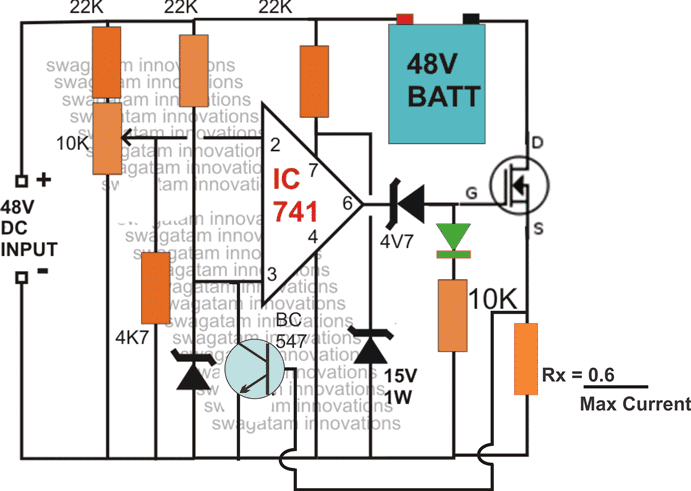
NOTE: The above diagrams mistakenly shows 48V as the input, the correct value is 56V. Because the full charge level of a 48 V battery is around 56/57 V.
NOTE: You will have to connect the battery first and then switch ON the input supply, otherwise the mosfet will fail to initiate for the charging process. Make sure the green LED remains illuminated after power switch ON, this will confirm the charging status of the battery.
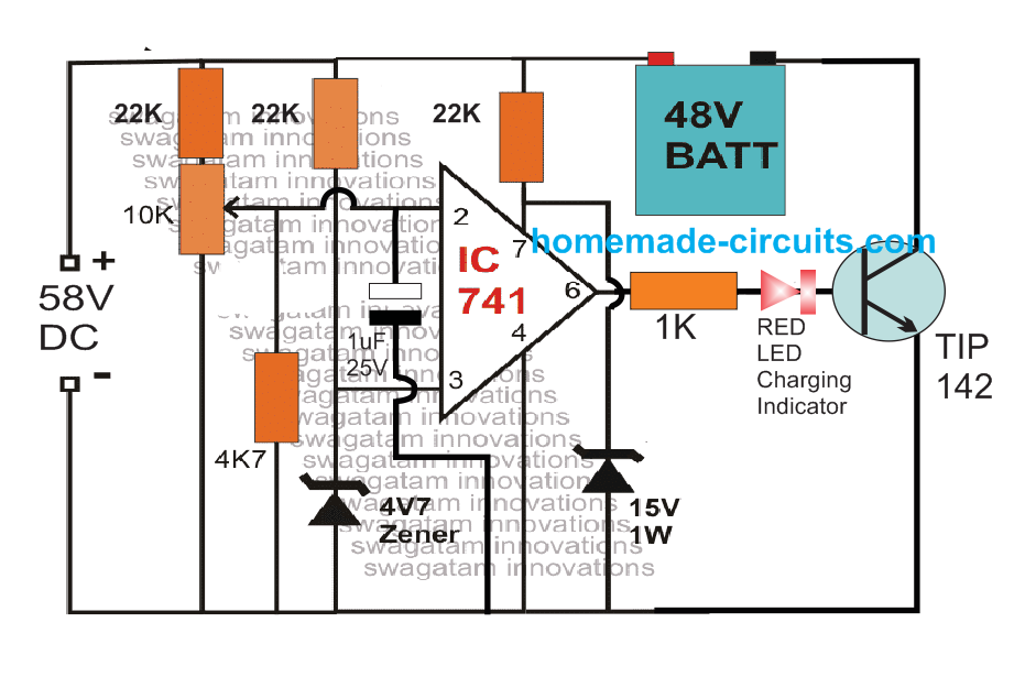
The above design can be also built using a TIP142 and a red led charging indicator.
Simple 48 V 100 Ah charger Circuit using OP Amp and TIP142
3) Making a Fully Automatic Version
The above circuit can be upgraded into an over charge cut off, as well as low charge restoring battery charger system, for charging 48V batteries.
The modifications enables the circuit to switch OFF the battery charging process at the set over charge threshold and restore back the process when the battery voltage falls below the low threshold value.
The 10k preset must be adjusted to set the full charge level while the 22k preset for detecting the lower threshold of the battery.
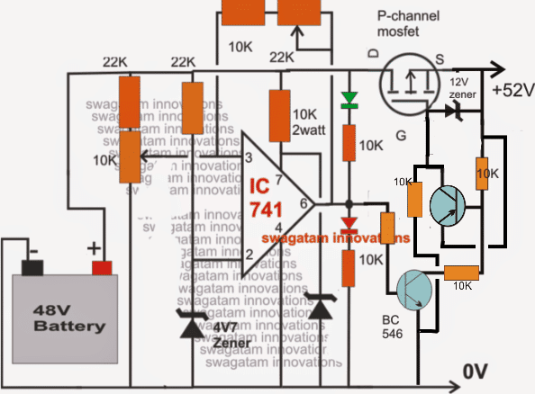
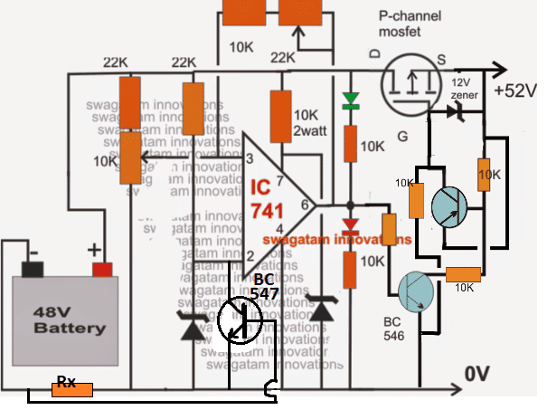
NOTE: In the above two circuits, please connect the RED LED in series with the BC546 base. This will prevent the op amp offset voltage from reaching the BC546 base and false triggering.
Simplifying the Design
The above design can be further simplified as shown in the following image. Notice that the input pins of the op amp are swapped in this design, which allowed the elimination of the extra PNP BJT from the circuit.
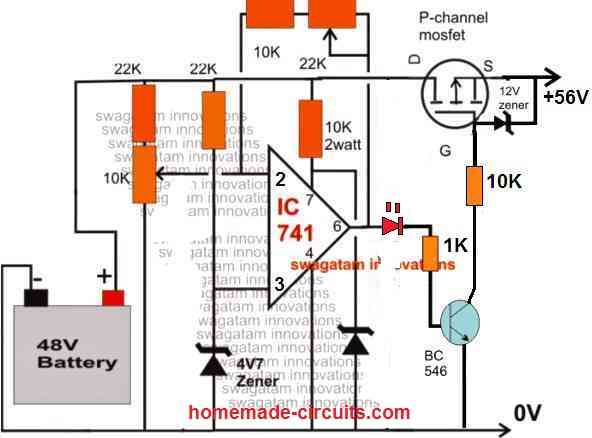
The above circuit can be also built using PNP BJT instead of a MOSFET, as shown below:
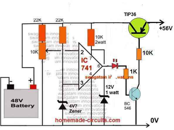
You can also add an current control feature to the above circuit, as shown in the following diagram:
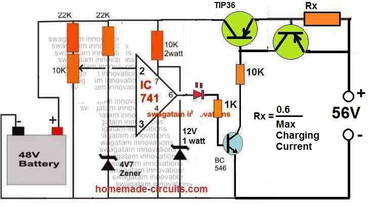
How to Set up the above Circuit:
For setting up procedure, the sample power supply should be connected across the points where the battery is connected, the mosfet does not require any attention initially. DO NOT connect the battery while carrying out this procedure.
Also keep the 22k preset link disconnected initially.
Apply the higher threshold level across the above mentioned points and adjust the 10K preset such that the RED LED just switches ON. Seal the adjusted preset with some glue.
Now reconnect the 22k preset link back into position.
Next, reduce the sample voltage to the lower threshold value and adjust the 22k preset such that now the green LED just lights up, while switching OFF the RED LED.
If you find no response from the circuit try using a 100K preset instead of the 22k preset.
Seal the adjusted preset as above.
The setting up of the circuit is over and done.
Please note that during actual operations, the above circuit will remain functional only as long as a battery stays connected at the shown points, without a battery the circuit will not detect or respond.
Feedback from Mr. Rohit
I have a 50-52v solar panel setup which is charging a 48v 78ah battery. What I want is when my battery is fully charged that is it reaches to 54v the battery charging stops and the supply which is coming from the solar panels is directed to another port from which we can charge any other device connected to the port. This charging should only continue till the battery is above 48v. Once it reaches 48v the battery again starts charging on solar panels and the supply to the other port is stopped.
Hoping you will reply soon.
My Response to the above Circuit Request
You can try the last circuit from the following artcilehttps://www.homemade-circuits.
Regards


good work sir.
Thanks, I got irf9540n which is 23A 100v can it handle it?
IRF9540 is p channel device and will work, but you will have to swap the input pins of the op amp, and connect the battery across drain and ground of the circuit. Source will go to the positive line.
Pls how do I select mosfet for 200Ah 48v.
My mosfet got fried during changing
you can use NTP52N10 MOSFET, which is a 100 V 60 amp mosfet
Hey, I need to modify this circuit for charging batteries from 48V and 10000mAh, what can I do?
Please aswer.
Hey, you can use the first circuit without any modifications.
Hi Swagatam,
I would like to know if you have any ideal about Transformer less Li-ion battery charger circuit diagram of 48V, 100Amps output
Hi Sujit, 100 amp is too high for any transformerless circuit except SMPS. However, the ideal method is the transformer based only, which is the safest and the most reliable.
Thanks for your prompt reply. Will follow your guidance and send you the feedback. I once again truly appreciate your remarkable support
You are welcome!
1) In 5th Circuit what is the details of PNP transistor (Other than BC546 & BC547)?
2) Also, can you suggest suitable P-type MOSFET for 50Amps Idss? I have used IRF9540; but it is only for 23Amps.
I am working on a 30Amps Lithium Battery Charger; hence, looking for 50Amps P-type MOSFET.
Thanks
Do I need to modify any other components to make the circuit suitable for 48V, 30Amps Li-ion Battery Charger. Thanks
No changes will be required for your application.
1) It is BC556
2) you can put two IRF9540 in parallel
Thanks a lot
How to design a CC and CV mode for charging the same 48V battery?
try this
https://www.homemade-circuits.com/0-300v-variable-voltage-current/
replace 300V with 60V, and calculate the 3.3 ohm as per battery current
Hi swagatam,
In the same manner i need , i have 2 lithium phosphate battery one is 60v 24ah and othr is 72v 24ah batter for this i need same automatic charging i need circuit, if over charge auto cutoff. Can you make for me
Hi Suman, you can use two such circuits and use them for charging the two batteries separately.
Hi Charan, Please specify them, I’ll try to help!
reduce the 22K at pin7 to 10K and check again
Charan, your simulation is showing wrong results, build it practically, it will work perfectly…
By the way where is the battery in the simulation? and why did you use 100 ohm for Rx…if your inputs are wrong the result will be wrong…
Charan, leave the simulator aside and build the circuit practically, it will work perfectly provide you do everything correctly. The smaller version of the is already tested. 110A is perfectly safe for a 220Ah battery, if you have the source with you. You can completely eliminate the Rx and the associated BC547 if the source itself has a fixed or limited 110 amps.
Hello sir,
From the 48v circuit for battery charger, will it be possible to charge 4 12v baterries of 100ah in series? What will likely go wrong assuming the transformer is upgraded
Hello Jerry,
That’s possible, nothing will go wrong, just make sure the current is fixed at around 10 amps or at the most 15 amps
Hello, Please can you help me to get a simply 30A mppt solar charger schematic?
If you need a really simple concept, then you can read the following article:
https://www.homemade-circuits.com/homemade-solar-mppt-circuit-maximum/
Gone through the great article, will build the last design, test and let you know. Thanks so much, Sir Ji.
Thanks Paul, wish you all the best.
Hi Sir, we have an e-bike with 48v(12v x 4pcs 20ah) gel type battery. my problem is we have to monitor the charging process because the charger that comes with the unit is just an ordinary charger no auto cut-off no over charged protection etc. can you suggest a circuit that i can incorporate to my existing charger to make my battery safe from over-charging or to have an auto cut-off when fully charged?
Hi Amor, you can use the second circuit from the above article it will never allow the battery to get over charged if properly set.
thank you Sir, so the output of my existing charger will become the input voltage of the 2nd circuit Sir?
Yes that’s right Amor, the charger output must be around 57V.
Hi Sir, my battery is 4x12v 20ah (48v) what is the value of RX in my case?
what particular P-channel mosfet can i use IRF9540 or IRF5210?
Amor, you can use a 0.3 Ohm 1 watt resistor. You can use 3nos of 1 ohm 1 watt in parallel.
…I would recommend the second circuit, so p-channel won’t be required
Hi Sir, what is the minimum and maximum input voltage i could use in the second circuit above? i have a regular charger with 60vdc output @ 2.8amp for ebike 48v 20ah, (4x12v)
how big must be the heatsink for the mosfet?
what will be the ideal battery full charge cut off for 48v 20ah gel type battery? 50v or 54v?
Hi Amor, the maximum input voltage should be 57 V, minimum should not be lower than 56V otherwise the battery will not charge fully.
The heatsink will need to be determined with practical testing, I am not sure about the size.
Full charge cut off should be at 57 V, or 56 V will also be OK.
Thank you Sir, is there any way that i could use it with my existing charger with 54v – 59v output indicated on its label. what is your recommendation Sir?
Hi Amor, if your charger supports 59V and has an automatic cut off then you can use it.
Is it possible to use a series of diode to make my 59vdc regular charger limit its output to 57vdc so that i could use it with your 2nd circuit above? if yes, what particular diode and how to do it Sir?
59V won’t be a problem, because the second circuit preset will be adjusted to 57V, so it will anyhow cut off at 57V automatically, but make sure the input current is around 1/10th of the battery Ah or at the most be 1/5 Ah
how is the correct input voltage/amp for this 1st circuit
It will depend on the battery specs being used…
Hey Swagatam, I tried simulating your second circuit using LTSpice and couldn’t get the circuit to behave properly. A varied Rx between many different values and didn’t observe any consistent changes in the current being fed to the battery pack. I also tried getting rid of the diode connected to the gate of the mosfet and didn’t observe any changes with that either. What kind of diode did you use there? Also, what software did you use to simulate the second circuit? Thanks for your time.
Hi Nathanael, it is a simple design and should start working immediately when you test it practically. Rx is in series with the battery so changing its value will instantly effect the charging current, but only while the mosfet is ON. The gate zener diode is employed to block the offset leakage voltage from the opamp output so it’s important. I design and build circuits using my knowledge, experience, and calculations. I don’t use simulators, because often they produce misleading results.
Thanks for your feedback, I was able to get the charging current to change according to your equation. What is the purpose of the green diode in series with the 10k resistor? I’m currently working to build a charging circuit for a 37 volt lithium ion battery pack. I can supply just about any voltage to the circuit with buckboost converters, but I need the circuit to be able to detect when the charge voltage is above or below the 37 volts and either stop charging or start charging appropriately. Do you have any recommendations? Thanks again.
The shown preset can be used for adjusting the cut off threshold at 37V precisely.
The green diode is a green LED which illuminates while the battery is charged, and shuts off when the battery is full
Hey Swagaram, I constructed the circuit and it works great! I started by having a 35 volt supply to charge my 37 volt battery and was able to get it to operate as desired for extended periods of time. I had to change out the rectifier for my source and now I am getting a 50 volt source for the circuit. I’m still charging the battery up to 37 volts, but I’ve run into a problem where my 4.7v zener running from pin 3 to ground burns out after a short period of time. I was wondering if it mattered which order I connected the battery and the source voltage (I’ve been connecting to the source first and then connecting the battery).
Glad it’s working Nathanael! The pin#3 zener is protected by the 22K resistor so It’s strange if it burns. It shouldn’t burn because the 22K would drop the current to a great extent safe enough for the zener. Still, you can try using a 1 watt zener and see how it responds.
The battery should be connected first and then the input switched ON, although this may be not related to the zener burning, this is necessary to enable the the charging of the battery. If the supply is switched ON first, the opamp would sense a high voltage at pin#2 and switch OFF the mosfet, which would then disable the battery charging permanently until the input supply is switched OFf and ON again
I did some more trouble shooting and it turns out its the BC547s that are burning out. I connected the battery (slightly undercharged at 35 volts) and then connected the terminals for the supply and heard a pop from the circuit. I pulled the BC547 and it has gone bad. Any ideas on how to protect the BC547? I know now the zener at pin 3 is working properly.
Referring to the second circuit from top, the BC547 has no chance of burning because its collector emitter is clamped and protected at 4.7V by the zener, and its base is almost connected to the ground via RX.
The only way it can burn is if Rx is faulty or open, in which case the entire voltage from the fet can enter the BC547 base and burn it.
So I can’t figure out how it may be burning in your case?
Please check the voltage across the C/E and B/E of the BC547, this will verify the actual conditions.
Replacing the 540 mosfet seemed to fix whatever was wrong with the circuit. I’m assuming the Rx=0.6/(max current) is somehow derived from equations regarding the BC547?
Glad you could solve it. Yes the 0.6 value is the approximate full switch ON base voltage for the BC547
hai sir
i want to use this circuit for 12v 17ah battery. please discribe the required modifications.do u have pcb for this circuit
rajesh
Hi Rajesh, if you want to keep your battery always charged at the correct level and cut off when it reaches an overcharge, you can make the first design. Remove all the 22k resistors and replace them with direct links, and also remove the 15V zener at pin#7 of the IC. That’s all, now you can set it up as described.
Thank you very much for helping people. God bless you.
sir can this circuit be used as a BMS for lithium ion batteries and can it be wired in series or parallel the way BMS is usually wire sir
Marvin, yes it can used, but the cells cannot be monitored individually for series connected modules, same for the parallel connected modules, however the entire module can be monitored as a whole
24vdc बैटरी को चार्ज करने के लिए क्या चेंज करना होगा डिज़ाइन में 150 w 12 vdc के 2 पैनल हैं
use the second circuit from top, replace all 22k resistors with 10K, and optimize Rx as per your battery’s Ah rating
Sir, we want to design 48V battery level indicator. As after full charge battery voltage reaches to 54V. Our team is manufacturing a solar car with a battery of 48v. Our problem is when ever driver press throttle the battery voltage in battery level indicator fluctuate very much and then the car is stationary it doesn’t. So we want such battery level indicator which do not fluctuate when throttle is applied and show battery percentage while driving the vehicle.
Hope you reply soon.
Thank you Sir
Yashvardhan, if your battery level indicator is fluctuating due to an actual drop in battery voltage while throttling then that cannot be corrected, because if the battery voltage drops suddenly and rises then the indicator will also show corresponding sudden drop and rise in its reading….so first yu will have to investigate why the indicator is fluctuating, is it due to actual battery voltage drop or due to some other reason such as RF disturbance or noise spikes?
Gud day sir, I av 2000watt stabilizer transformer, I want to use the transformer for 1kva inverter, when I calculated it d primary currently is 4.5amp while d secondary current us 83amp but I dnt no size of copper Guage to use
Hi Abdul, you can use the trafo for inverter purpose, but for inverter the mentioned specs for primary will become for the secondary and vice vers….wire size is not important, the measured are enough for the verification
I did get u sir, what I mean is Dat I want design a 1kva inverter using 2000watt stabilizer transformer. And I want to wind it myself. So hw can I get d number of turns and size of wire to be used. Sir I nid ur help
sorry, my knowledge about rewinding trafos is very low, so can’t help you in this regard
Good day sir, please how can I modify it to charge 24v of 200ah battery
Dayo you can try the second circuit from top, and use it for your 24V/200AH battery.
use IRF540 on heatsink for the mosfet.
dimension the current sensing resistor for limiting 20 amp current
feed 28V/20amp to the circuit
Thanks for the response, but the second circuit does not have overcharge cutoff and low level feature. How will that be possible sir.
Hi Mr Swag,
I constructed the last circuit today(for 12v battery)though without the current control bcos I could not found appropriate RX.
With high threshold the red led came up but became brighter when I adjusted he 10k preset ok.
But with low threshold, I adjusted the/22k/100k preset yet the red LED did not go off. Both LEDs came on. What did you think I did wrong?
Do I need the 12v zener diode across gate and source of p channel bcos am using 12v supply.
Thanks
Connect a 3V zener diode at pin#6, such that the signal from pin#6 passes through this zener to reach the other connected parts. cathode will go to pin#6
the 12v zener is required otherwise your mosfet will burn
Thanks so much
You are welcome!
Bro Segun, check this out, it will help out if you have gotten rx.
http://www.www.homemade-circuits.com/2017/01/universal-battery-charger-circuit.html
Dear Swagatam,
How is possible to limiting to charging current with 3 amper.
I want to charge 4 x 50 Amper battery set with 7 Amper transformer but I want to limit charging current with 3 Amper with this circuit.
Dear Yildirim,
in the second circuit use Rx = 0.6/3 = 0.2 ohms, wattage = 0.6 x 3 = 1.8 watts
therefore replacing Rx with a 0.2 ohm/2 watt resistor will do the job
Hi swag
Using the last circuit from top, pls where is the Rx resistor? Is it the resistor connected to emitter of BC 546 to gate of MOSFET.
Thanks
Hi Segun,
Rx is near the battery in the last diagram 🙂
I still don’t get it. Is the 22k connected to 10k preset or 22k connected to zener diode 4v7 at the inverting input of op amp from 4th diagram from top.
for a 12V battery you can remove all the 22K resistors except the 22K preset. and also remove the 10k and zener at pin#7…all these resistors were used to safeguard the IC from the high 48V source. pin#7 can be directly connected to the positive line.
and please do it only after proper understanding of each and every steps and stages…otherwise you may fail to get things working for you.
I still don’t get it. Is Rx resistor the 22k connected to 10k preset at non-inverting side or 22k resistor connected to zener diode 4v7 at the inverting input of op amp for 4th diagram from top.
I think you should try the second circuit first which is much simpler, the low voltage restoration can be added by adding a feedback link from pin#6 to pin#2
Thanks Swag
So, P-channel MOSFET what part Not can I use if I am to convert the circuit to 12V up to 200AH battery charger with current limit = 30A
Hi Segun, I have already explained which parts should be removed, please check my previous comments.
the mosfet s not P-channel, it is N-channel IRF540
I really commend you for your great work and interest.
Straight to the point.
I am using the last circuit from the top (i.e 4th circuit) for 12V upto 200ah batt with xformer 15v/50A. I want to limit the current to battery to 30amp.
Now(1) how do I calculate the current 30A limit
(2) you told me to remove all 22k resistors with links and 15v zener and use N channel irf540 MOSFET right?
Segun, you can calculate 30A limit by calculating Rx…see Rx formula in the 2nd diagram…
Hi pls how can we adapt this circuit to charge any battery of 12v upto 200AH
(1) what will the zener diode volts would be
(2) wattage of resistors and preset resistor and ohm size
(3) can it limit the current drawn from battery to 20A
for a 12V battery you can remove all the 22K resistors and replace them with a link.
also remove the 15V zener, and the 4k7 resistor.
rest all be as given , all resistor are 1/4 watt.
pin#3 zener can be any zener between 4V and 9V rated at 1/2 watt
I need to charge a 48V lithium Ion battery pack. It needs to have a current limiter installed. Can you tell me how to modify your circuit to control current? Then constant voltage after bulk charging?
Thank you!
Tim
I have modified and updated the first diagram, please check out the second one from top.
Gud day sir, I av a project am working on title inverter type arc welding machine. I av finish constructing it. And is 48v system. When I tested it is working properly after a week later later I tested is jst starting but no melting the electrode as before. My question is wat can be d problem, bcos am thinking maybe the battery is low. Can u giv me ur opinion. Thanks.
Hi Abdul, yes most probably it could be due to low batt, because a welding inverter is supposed to draw heavy current and in the process the battery may drain relatively quickly…you can verify it with a voltmeter and possibly keep a voltmeter permanently connected with the system.
Hello Sir,
Request
Sir can you refer a circuit for the following situation
I have two battery packs, Let us assume one of them is charged. Now there are two parts one is the generator which charges the empty battery pack and the other part is the motor which uses the charged battery pack. Now what i want is when the motor has used the battery to the fullest i want a automatic battery switching circuit which switches the connection with this battery with the other one(being charged by generator till now). So that now newly charged battery from generator is used by motor and the other one starts charging.
Please help.
Jai, you can try the following concepts and customize them as per your battery specifications:
https://www.homemade-circuits.com/?s=twin+battery
https://www.homemade-circuits.com/automatic-dual-battery-charger-with/
Thanks sir, I we try it n see.
But sir i av 48v 100ah battery and I want connect dc fan rated 12v, 0.13amp to my inverter to b fan d mosfet .i nid a circuit diagram to limit d current. Bcos it as damage 2 dc fan. Pls I nid ur help sir
Abdul, only voltage will need to be controlled, not current.
you can use the following configuration for your fan
https://www.homemade-circuits.com/2012/08/simplest-dc-cell-phone-charger-circuit.html
the input will be your 48V input, resistor should be replaced with a 10K, and zener with a 15V zener.
transistor must be a TIP122C
Gud day sir, I av issue with the charging circuit setting , after complete the circuit via third circuit, I disconnected the 22k,then I vary the 10k the red led turn on, so I connected the 22k back, the green light turn off and the red light good off. But the question is the green light always on even I vary the 22k.pls I nid ur help about the setup
Abdulnoni, disconnect the positive side of the green LED from the existing position and connect it with pin#7 of the IC..this will solve the issue but the illumination might decrease….to correct this decrease the pin#7 resistor to 4k7, and also decrease the LED resistor to 4k7….do this and check the response…
and also remember that the 22k feedback preset is arbitrarily selected…you can try other values such 100k preset or 220K preset for getting the correct lower threshold restoration adjustment of the circuit.
Could not get irfp9540,can I use irfp9240 for replacement
please check the datasheet of the device, if the current and voltage specs suit your application then you can use it….
Thanks sir, I we try it n see
Sorry sir, is a mistake the battery is 12v 100ah x 4 to in series to give 48volt 100ah. What type of mosfet will I use via third circuit
OK, in that case you can use a IRF9540 mosfet
Hello sir, I want to construct a 48v automatic battery charger and my battery rating is 12v 100ah via ur third circuit what type of mosfet will I use
Hello Abdulnoni, why do you need a 48V charger for a 12V battery?
I have a circuit ,where I am getting the 52v 700mA output at my power supply but the problem is about the current. I require 5-7A to charge my battery pack because its is 19A pack.
Please Kindly help me sir.
Please suggest me a design to get 5-7A 52V supply to charge my battery pack using 1st or 3rd circuit diagram
To get higher current you will have to use a higher current power supply, there’s no way to increase 52V 700mA to 52V 5 amps, that’s just not possible.
you can buy a 48V 7amp transformer and use a bridge rectifier and a 2200uF/100V filter capacitor for rectifying its output, this will provide you the required 56V/5 amp.
Thank you so much
But I want to make the charger with my own hands not to buy
For making a charger you must have the power supply first, for that you will have to buy a 48V / 7 amp transformer.
please kindly refer me a best one
you can use the first design
I tried the first circuit in that the LED is goes on during charging and when the battery is fully charged the LED goes off!
Is I mentioned in the above statement is right? or not?
that’s perfect, If the green LED i getting OFF it means the opamp is correctly responding to the fully charge level, and the mosfet must also switch OFF in this state.
I had set the #pin 2 as 4.7v without connecting the batteries and then i connected the battery pack.
After the battery pack is fully charged up-to 48v but the circuit doesn’t cutoff
sorry, that’s not the correct way to set.
you must feed 48V to the circuit without battery connected, then adjust the preset until the green LED just shuts down. That’s all, your circuit is now set.
By the way for a 48V battery the full charge level should be 56V.
The circuit doesn’t cutoff even after the battery pack is reaches to 48v. Please help me
how did you set the preset??
i had seted the preset without connecting battery pack
OK, please tell me how you implemented the procedure?
I need 53v li ion battery charger. I have 73v DC supply with 5amp. Can you please help me
you can try the first concept for your application
This is very help full article. Thanks for your great support for beginners like me.
Can i use the first circuit for 48v 7amps supply, which is going to be charge the 18650 Li Ion batteries of 48v 19amps.
Thanks Richards, yes you can use the first design for charging and cutting off the mentioned battery automatically
please tell me the mosfet no of n type
use IRF540 for n channel
Do you have a parts list for this circuit?
thank you
Carl
Parts are all standard, the resistors are 1/4 watt CFR, the zeners are 1/2 watt
Thanks Swagatam………
Would it be hard to set this design up for 12 volts?
Could the self regulating design be tweaked to shut off high and turn on low?
Carl
BTW where are you located?
Hi Carl, there are plenty of similar circuits published in this website which you you can refer and customize as per your preferences…all of these employ opamps are self regulating type and the distance between the full charge and low charge can be adjusted as desired.
you can check out the top sidebar section for getting all the links related to automatic battery chargers…
…I am in India…
Hello good sir, can you recommend trans other than BC546 and BC556? Thank you in advance!
-Ru
Same circuit if I use 48 volt & 10Amp current then what will be the output voltage?
same as explained in the article
Hi hello mr swagatam. I'm back again ask you again..let me ask you sir.. is this capable to charge 48V with 365AH? IF not what components to be replaced?thanks in advance sir
Hi Mark, yes you can use the designs for charging a 48V/365AH battery, but make sure that the input source has a current not more than 40 amps.
and also make sure the mosfet is mounted over a large heatsink
Hi Mark, you can use the circuits which are explained in the above article for charging any battery from 12V to 48V, simply by adjusting the indicated 10k preset accordingly
Hi hello mr swagatam..im back again..let me ask you sir.. do you have a circuit that will be able to charge 12v, 24v, and 48v,.. I really need it mr sir swagatam.. thanks again
Engineer Swagatam, thanks i ve gotten the capacitor thanks God bless u
OK thanks!
Sir pls i have not seen the answer to that pin 14 and pin 10, that capacitor is it the one of polarity which pin is negative and positive please sir help me/. the first question that i asked before about the value of the CT and RT u have answered me that i should try any value but the pin 14 and 10 i did not know its polarity please help me sir or i should try any polarity? u know u are our lecturer thanks.
Please comment under the article to which your question is related, I will check it and answer you….
…And pls Engineer Swag, this circuit of IRS2453 the capacitor in pin no 14 and pin no 10 is it ceramic or micro-farad with polarity?
please comment under the referred article…
pls Swag, help me with 280vdc to 48vdc circuit to charge my 4 batteries
Olufade, I have already answered to this question in your earlier comment posted under a different article