In the following post I have explained a simple yet useful car speed limit warning indicator circuit which can be used in vehicles for getting an instant indication of a possible over speed limit conditions. The idea was requested by Mr. Abu-Hafss.
Technical Specifications:
Shall appreciate, if you could design a circuit to warn with some melody that the car has reached preset speed limit. As soon as the speed is reduced below the limit the alarm should go off.
The circuit should have 2 options for switching between 2 speed limits.
1. The circuit should have a selection switch --- Postion A >> 100Km/h (for ordinary highways) and Position B >> 120 Km/h (for Experessways).
2. When the switch is positioned for example at position B, a sensor which can get current speed from car speed-o-meter and then compare with the selected speed limit (120 Km/h). Whenever, the sensor reads the speed to be 120 Km/h or more, it will start playing a warning melody until the speed is reduced.
The Design
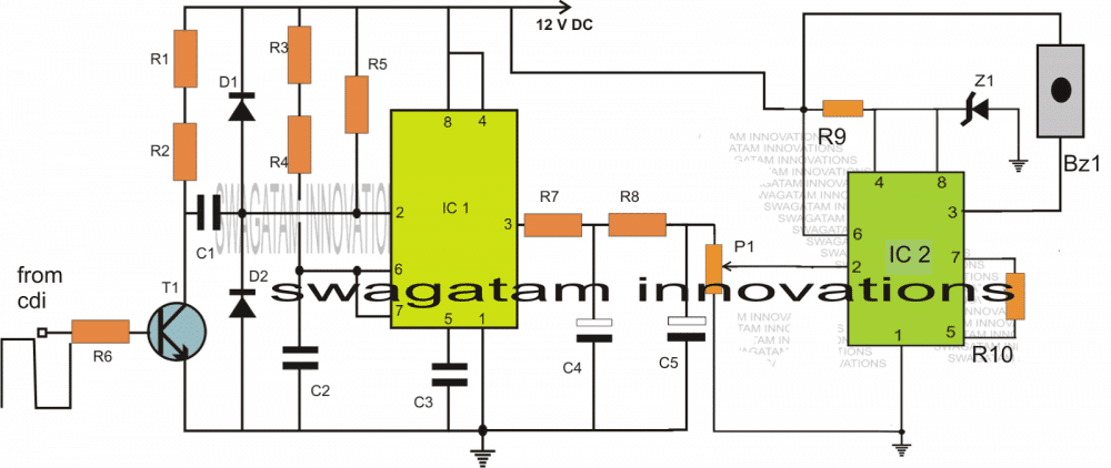
The designed circuit of a car over speed limit indicator basically consists of two stages. Both the stages incorporate the ubiquitous IC 555.
The stage which includes IC1 is configured as a simple frequency to voltage converter or a frequency dependent voltage generator circuit.
Here IC1 is rigged in the form of a standard monostable multivibrator whose ON time is decided by the resistors R3/R4 and the capacitor C2. These components must be selected appropriately for getting most favorable output response.
As we all know that all modern motor vehicles today incorporate electronic ignition systems which invariably include a CDI or a capacitive discharge ignition network, in contrast to the older circuit-breaker units.
The the CDI unit is responsible for generating the required igniting sparks inside the engine of the vehicle and its rate of firing is directly proportionate to the speed of the vehicle.
It means with an increase in the speed of the vehicle the charge/discharge rate of the CDI capacitor also increases and vice versa.
The monostable built around IC1 exploits this feature of the CDI system and derives a sample potential from the CDI at the base of T1.
T1 effectively switches the varying high voltage pulses from the CDI into low voltage triggering pulses across C1 and ground.
With response to the above pulses, every time T1 conducts it pulls pin#2 of IC1 to ground initiating the monostable output to go high.
The monostable sustains the output in the high position for a period determined by the values of the respective timing components as explained in the previous section.
However, the continuous train of pulses initiates an appropriately stabilized high output at pin#3 of IC1 (due to the functioning of the monostable which produces almost an exact average DC output proportional to the frequency of the pulses.)
Circuit Operation
The output is further stabilized into a perfect measurable equivalent DC by the integrator stage comprising R7/R8/C4/C5 and also P1.
IC2 is wired up as a voltage comparator.
Its pin#2 is allowed to receive the varying voltage from the IC1 output.
P1 is set such that as soon as the output from IC1 rises to a certain limit which may be calculated as the over speed limit value, the potential; at pin#3 rises over 1/3rd Vcc
This instantly prompts the output of IC2 to go low, activating the connected alarm device.
This alarm would stay activated as long as the car speed does not come down below the preset limit.
As soon as the speed is reduced, the alarm stops sounding.
The preset P1 may be suitably replaced with a properly calculated potential divider ladder type network along with a selector switch for enabling the selection of different speed limits for different free-ways.
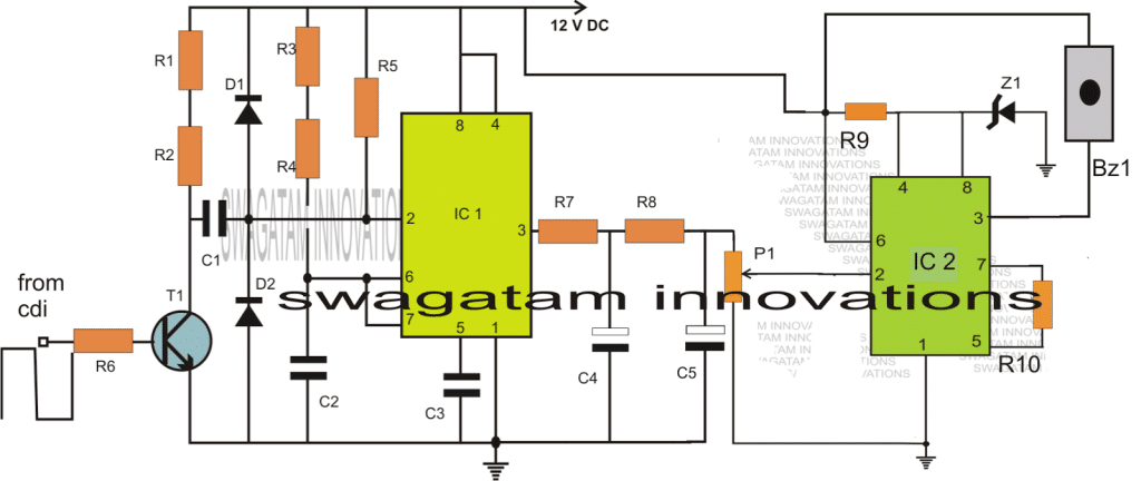
Circuit Diagram

Parts List for the proposed Car Speed Limit Warning Indicator Circuit
- R1 = 4K7
- R2 = 47E
- R3 = CAN BE A VARIABLE 100K RESISTOR
- R4 = 3K3,
- R5 = 10K,
- R6 = 330K
R9 = 1K, - R7 = 1K,
- R8 = 10K,
- R10 = 100K,
- C1 = 47n,
- C2 = 100n,
- C3 = 100n,
- C4 = 100uF/25V,
- C5 = 10uF/25
- VP1 = 10k PRESET
- Z1 = 6V ZENER
- T1 = BC547
- IC1, IC2 = 555,
- D1,D2 = 1N4148
- BZ1 = BUZZER OR MUSICAL ALARM DEVICE
Improving the Design By using an Opamp
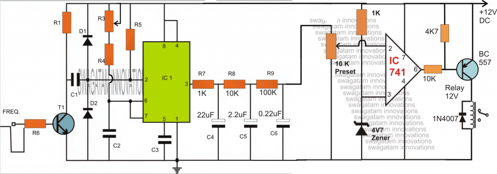
The accuracy and reliability of the above explained car speed warning indicator can be further improved by replacing the 555 buzzer stage with an opamp/relay stage as shown below:
Circuit Diagram

To make the relay latched on detection of an over-speed situation, a hysteresis feedback can be to the above design, as shown below:

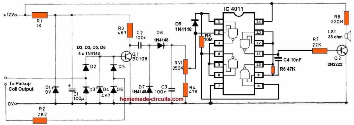
Speed Limit Indicator using IC 4011
Pulses from the pickup coil are rectified and clipped at 4V7 after passing through a current limiting resistor. A DC voltage equivalent to engine rpm is delivered to RV1 through Q1 and the diode pump; the sharp transfer characteristic of a CMOS gate is exploited to trigger the oscillator produced by the remaining half of the IC 4011.
A shrill sound which cannot be ignored comes through the speaker at the predetermined 'speed' (revs) threshold, and the sounds fades the moment the speed reduces by three or four mph.

Input pulse can be calibrated with a reliable pulse generator, noting that frequency = revs per minute multiplied by the number of cylinders divided by 120 for a four stroke engine. For a car having a configuration of 17 and 1/2 MPH per 1000 revs, in top gear, f =133Hz at 70 MPH, 124Hz at 65 MPH; for a car with a specification of 17 and 1/2 MPH per 1000 revs, in highest gear, f =133Hz at 70 MPH, 124 (4000 RPM and 3714 RPM).
Q1 must be supplied the required frequency, and VR1 must be adjusted to turn off the siren. On the prototypes, successful switching happens with a fluctuation of just 5Hz (1 50 RPM), maybe less than 3 MPH in the previous case.
Immediate 'on-the-road' measurement, while covering discrepancies due to wheel diameter, etc., will only be as accurate as the speedometer, and thus should clearly be done by a passenger instead of the driver.
