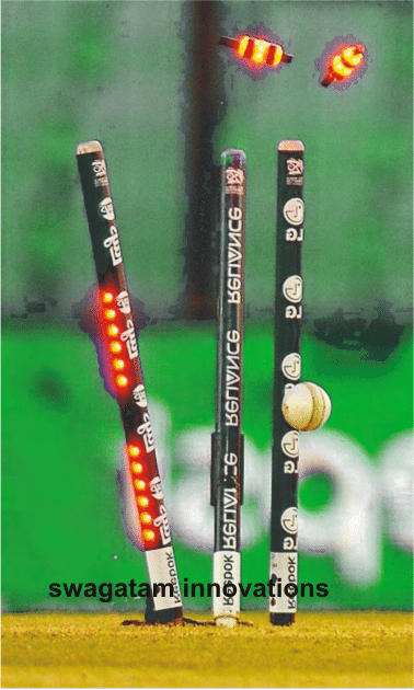
In this post I have explained how to make an illuminated LED cricket stump and bails for helping umpires declare a foolproof OUT, NOT-OUT decisions.
The Circuit Concept
You might be seeing these amazing cricket stumps in the ongoing 2015 ICC world cup cricket matches, which can be seen dazzle or light up brightly as soon the ball hits any one of the stumps.
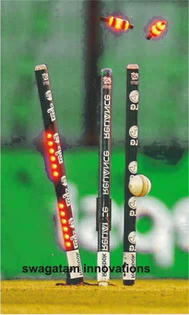
It's invented by an Australian person named Bronte EcKermann and created by South Australian manufacturer Zing International.
It is said that the cost of these stumps may be as high as US$ 40,000 for each set, gosh!. The circuit of these LED stumps is assumed to be consisting of all sorts of complex designs using microcontrollers.
In this article we'll learn how each of these circuits can be built using ordinary components at less than $5 and yet be as effective as the original LED stump specs.
LED Bails Circuit
The first diagram below shows a circuit which may be employed inside the bails, the idea may be understood as follows:
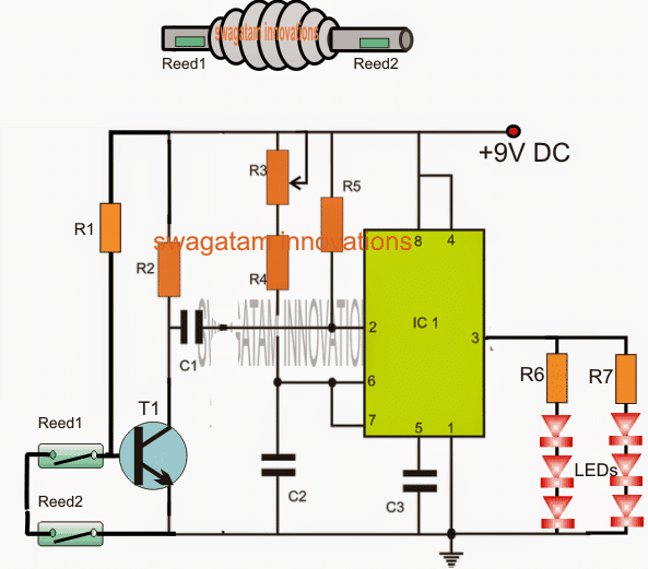
The IC1 which is an IC 555 is configured as a monostable wherein R3 and C2 along with R4 decides the ON time of the LEDs.
An NPN transistor T1 can be seen attached with pin2 trigger input of the IC, whose base is rigged with a couple of reed switches in series.
The idea is simple: The entire circuit is required to be fixed inside each of the bails with the reed switches enclosed inside the end tubes of the bails. Furthermore, a permanent magnet needs to be fixed at the upper ends of the stumps so that the reed switches remain closed for so long as these are held over the stumps.
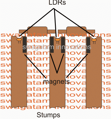
The figure above shows how the magnets inside the stumps needs to be embedded and positioned for the bails to respond to these.
As long as the bails are held over the stumps, the reed switches stay closed ensuring a switched OFF T1. However the moment the bail is completely dislodged from the slots, allows the reed switches to open and switch ON T1 which in turn triggers the monostable illuminating the LEDs for a time period as determined by R3/R4/C2. The LEDs remain shut off until these are yet again positioned over the stumps for a repetition.
That takes care of the bail circuitry, pretty simple.... isn't that?
In the above diagram we can also see LDRs being positioned right at the top of the stumps just under small apertures that my be drilled on top surfaces of the stumps.
These LDRs become exposed to the ambient external light the moment the bails are dislodged from the slots. since these LDrs are supposed to be integrated with sets of identical monostables inside the stumps, the operation becomes responsible for illuminating the LEDs attached on the stumps, thus the entire system consisting of the stumps and the bails become synchronized providing a foolproof sequence of the proceedings.
UPDATE:
Hey friends, today I made the LED bail design even simpler by using transistors instead of an IC. The advantage of this circuit is that it can work even with a 3 V supply and also blink the connected LEDs during its ON period. Additionally, I have ensured that the standby current of the circuit is negligibly low (while these are mounted on the stumps)
Here's the new circuit diagram for your viewing pleasure!
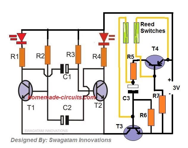
Important: Please keep both the reed switches together on a single arm of the bail and linked with a single magnet on the stump, instead of installing them across the opposite arms of the bail. Because both the reed switches need to close while they are placed on the stumps, if one of the reed is open then the circuit might not respond correctly.
Video Proof or the Test Results of the above LED Bail
Parts List
- R1, R4 = 100 Ohms
- R2, R3 = 56K
- R5, R6 = 10K
- R7 = 330K
- C1, C2 = 10uF/6V
- C3 = 1000uF/6V
- T1, T2, T3 = BC547
- T4 = BC557
- Miscellaneous = Reed Relay switches, 3V Button Cell
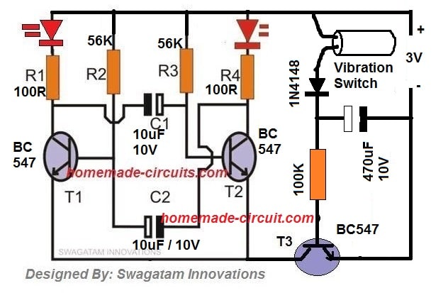
The above LED Bail circuit can be further simplified by using a vibration switch, as shown below, although I doubt the accuracy level may not be as good as the reed relay version.
Vibration Switch Image

Circuit Diagram
LED Stump Circuit
The following circuit shows how the circuit inside the stumps needs to be configured for implementing the LED stump circuit operations.
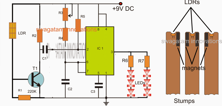
In the diagram we are able to witness the integration methods of the LDRs with a 555 IC based monostable.
As long as the bails are held over the stumps, the ambient light stay blocked from the LDRs which keeps T1 switched OFF. but the moment the bails are thrown of the stumps, the LDRs become exposed to the ambient light enabling T1 to receive a biasing voltage which in turn triggers the monostable so that the LEDs are illuminated for the set period of time fixed by the relevant components.
The LEDs shut of after the set time has elapsed until the bails are restored over the stumps for yet another cycle.
Designed by: Swagatam.
Parts List for the above explained LED cricket stump circuit
- R1 = 220K
- R2, R4, R5 = 10k
- R6, R7 = 220 ohms
- R3 = 1M preset
- C1 = 1uF/25V
- C2 = 100uF/16V
- C3 = 0.01uF
- T1 = BC547
- IC1 = NE555
If you have any doubts regarding the working or the manufacturing of the circuit, please feel free to contact me through comments, will be happy to help!
