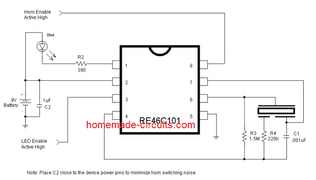
The single IC piezo driver with LED explained here can be used as a warning indicator device in conjunction with some sensor for generating an audible as well as a visual indication.
How the Circuit Functions
- The circuit of this piezo cum LED driver, warning indicator circuit utilizes just a single chip RE46C101 from microchip, for implementing all the procedures.
- The chip has the feature of a built in piezo driver as well as a LED indicator circuit.
The chip is operated using a single 9 volt PP3 cell, which is applied across its pins 2 and 5. - The piezo driver output must be terminated to a three pin type piezo transducer and connected correctly as shown in the figure.
- The outer metal case of the piezo goes to the pin #6, the inner white portion which covers maximum surface goes to pin#7while the smallest section of the piezo at the center goes to pin#4 via R4.
- The IC will deliver a sharp, chilling frequency over the piezo producing an ear piercing warning sound.
- The audio is accompanied with a simultaneous LeD indication at pin #1 of the IC.
- The above execution takes place when a high logic supply is applied at pin #8 of the IC.
- This logic input may be derived from a sensor configuration for triggering this circuit.
- For example, this single IC piezo driver circuit may be used in conjunction with a smoke detector sensor, when a smoke or fire is detected by the sensor, it sends a high logic to pin #8 of the IC for enabling the required warning alert indications from the IC outputs.


Courtesy - ww1.microchip.com/downloads/en/DeviceDoc/22163A.pdf
Need Help? Please Leave a Comment! We value your input—Kindly keep it relevant to the above topic!