In this post I have explained a very simple digital panel type voltmeter circuit using a single IC L7107 and a few other ordinary components. The circuit is able to measure voltages right up to 2000 AC/DC V.
About the IC L7107
Making this simple digital panel voltmeter circuit is particularly easy due to the availability of the A/D voltage processor chip in the form of IC L7107.
Thanks to Intersil for providing us with this wonderful little IC L7107 which can be easily configured into a wide range digital voltmeter circuit using a few number of common anode seven segment displays.
The IC 7107 is a versatile, low consumption 3 and 1/2 digit A/D converter IC which has in-built processors such as seven segment decoders, driver for displays, set reference levels and clock generators.
The IC not only works with ordinary CA seven segment displays but also with liquid crystal displays (LCDs) and has an in-built multiplexed back plane illuminator for the connected LCD module.
It ensures auto zero correction for inputs less than 10uV, a zero drift for inputs below 1uV/oC, bias current for inputs of maximum 10pA and cross over error of less than a single count.
The IC can be set with ranges as high as 2000 V AC/DC, and as low as 2mV, the later makes the IC very suitable for measuring low inputs from sensors like load cells, piezo transducers, strain gauges and similar bridged transducer networks.
In other words, the chip may be simply configured for making products like digital weighing scale, pressure meters, electronic strain gauge, vibration detector, shock alarms and many similar circuits.
Needless to say, the IC L7107 can be also rigged into a simple yet accurate panel digital voltmeter circuit, which is what we are presently interested in.
Circuit Operation
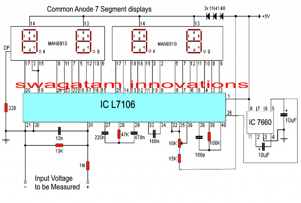
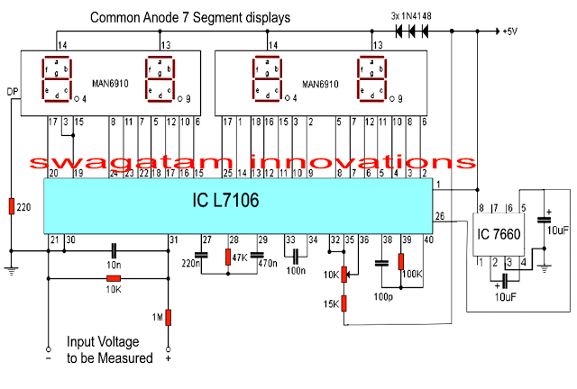
Referring to the circuit diagram below, the unit is a full fledged digital voltmeter circuit which can be used for measuring direct voltages right from zero to 199 volts.
The range can be appropriately widened or shortened simply by altering the value of the 1M resistor positioned in series with the input terminal. With 1M, the range gives a full scale of 199.99V, with 100K in place the range would become 19.99V full scale.
The circuit requires a dual +/-5V supply for operating, here the +5V may be strictly acquired from a standard 7805 IC regulator circuit, the -5V is automatically created by the IC 7660, and fed to pin#26 of the IC L7106.
The three 1N4148 diodes connected in series with the display supply line ensures optimal operating voltage to the displays for illuminating them with correct intensity, however for brighter illumination, the number of diodes may be experimented, as per personal preferences.
The 10K preset across pin#35/36 is used for calibrating the voltmeter correctly and must be set such that exactly 1V appears across pin#35/36. This will set up the circuit for displaying the measured magnitudes accurately as per the given specs, and datasheet of the IC.

Parts List
All resistors are 1/4 watt unless specified
- 220 Ohm - 1
- 10K = 1
- 1M = 1
- 47K = 1
- 15K = 1
- 100K = 1
- preset/trimmer 10K = 1
Capacitors
- 10nF Ceramic Disc = 1
- 220nF Ceramic Disc = 1
- 470nF Ceramic Disc = 1
- 100nF or 0.1uF Ceramic Disc = 1
- 100pF Ceramic Disc = 1
- 10uF/25V Electrolytic = 2
Semiconductors
- 1N4148 Diodes = 3
- 7 Segment Displays MAN6910 or Equivalent = 2
- IC L7106 = 1
- IC 7660 = 1
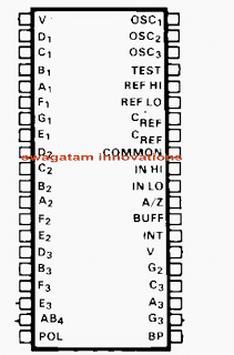
Pinout details of IC L7106 for interfacing with a 3 and 1/2 digital LCD display.

