A water level indicator is an electronic circuit which indicates the various levels of water inside a tank. This happens when rising or dropping water levels come in contact with the respective water sensors arranged step wise inside the water tank at different depths.
In this post I have explained 2 interesting ways to make simple water level indicator circuits using transistors, CMOS NOT Gates and some LEDs, the later section of the articles also discusses how to upgrade the circuit with a relay.
Circuit Objective
There are many posts in this blog which essentially explain water level controller circuits, with the specific intentions of switching the involved motor pump when the tank fills up.
However there are folks who just require an indication of the different levels of water in the tank rather than have an automatic shut off facility.
The switching OFF of the motor is preferred to be carried out manually, which is considered more reliable and safe by them.
For a Wireless Water Level Indicator you can Refer to This Article
1) Using Transistors
We know that undistilled water conducts electricity, although with some resistance. The resistance may be anywhere from 100K to 500K, depending on the purity level of the water. This property can be effectively used for switching transistors ON/OFF.
We use this characteristic of water to switch the base of a series of BJTs sequentially as the water level goes up and down across the sensors attached with the respective transistor bases.
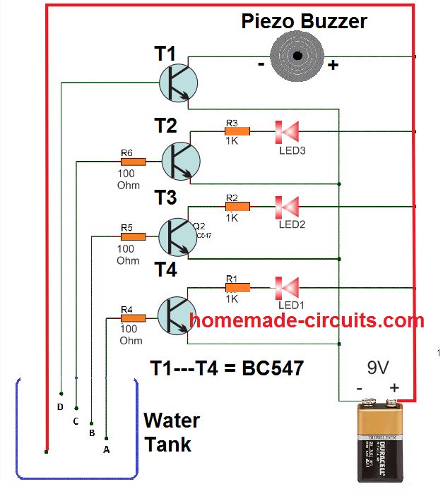
A simple circuit for this can be visualized below:
Video Illustration
The idea is as simple as it can be. The positive terminal of the supply can be seen immersed at the lowest level of the tank, so that water is in contact with this positive even at the lowest level. The bases of the respective transistors are arranged sequentially across the water tank depth, such that when the water fills the tank, it sequentially connects the positive supply with the relevant BJT bases through the rising water level.
When this happens the transistors begin getting biased one by one, illuminating the collector LEDs in the same sequence. When the water reaches the full level, the buzzer is immediately sounded by the topmost BC547.
This helps the user to get a clear idea of the water level, and also when the water has reached the overflowing level.
Parts List
All resistors are 1/4 watt 5%
- 1K = 3 nos
- 100 Ohm = 3 nos
- BC547 = 3 nos
- Piezo Buzzer = 1 no
- RED LEDs = 3 nos
2) Using CMOS NOT Gates
The proposed water level circuit idea is specifically suited for the above type of readers who are satisfied with the indications only and want to do the shutting part of the motor manually as per the readings of the indicator and as per the desired water levels in the tank.
- The circuit presented here is again super simple to build, involving only a single IC 4049 for the intended applications.
- The IC as we all know have six NOT gates, these gates are simple inverters, meaning they will invert any voltage level at their input pins to exactly the opposite level at their output pin.
- So if a positive is applied to the input, the output would instantly produce a negative and vice versa.
- The high input impedance of CMOS gates makes sure that potential even with very low currents are suitably sensed and interpreted by them.
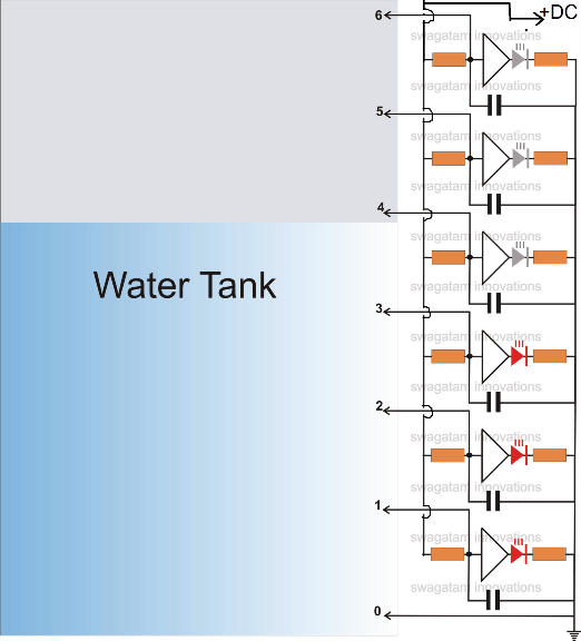
- The idea is simple, the ground or the negative voltage (point 0 in the figure) is held at the bottom most part of the tank, such that the water reaches this point first up when it starts filling.
- As the water level goes higher, it subsequently comes in contact with the inputs of the NOT gates arranged serially upwards.
- The negative voltage stationed at the bottom of the tank leaks through the water and comes in contact with the relevant inputs of the gates.
- This negative potential applied at the subsequent inputs of the gates means a production of an opposite voltage, that is a positive potential at their outputs, that's what exactly happens.
- The positive voltage thus generated lights up the concerned LEDs, indicating which input of the gate at what level has come in contact with the rising water level.
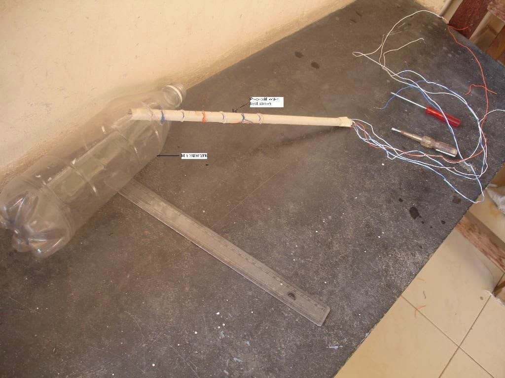
- The sensor wire terminals from the circuit in the form of the points 0 to 6 may be arranged over a non conducting stick made up of plastic with brass screw heads fitted as the sensor termination.
- The LED illuminations give a direct indication of the water levels, as these are stationed with calibrated positions in the tank (see circuit diagram)
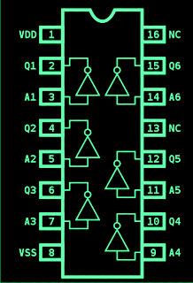
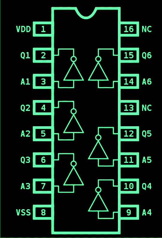
The pin out diagram of the IC
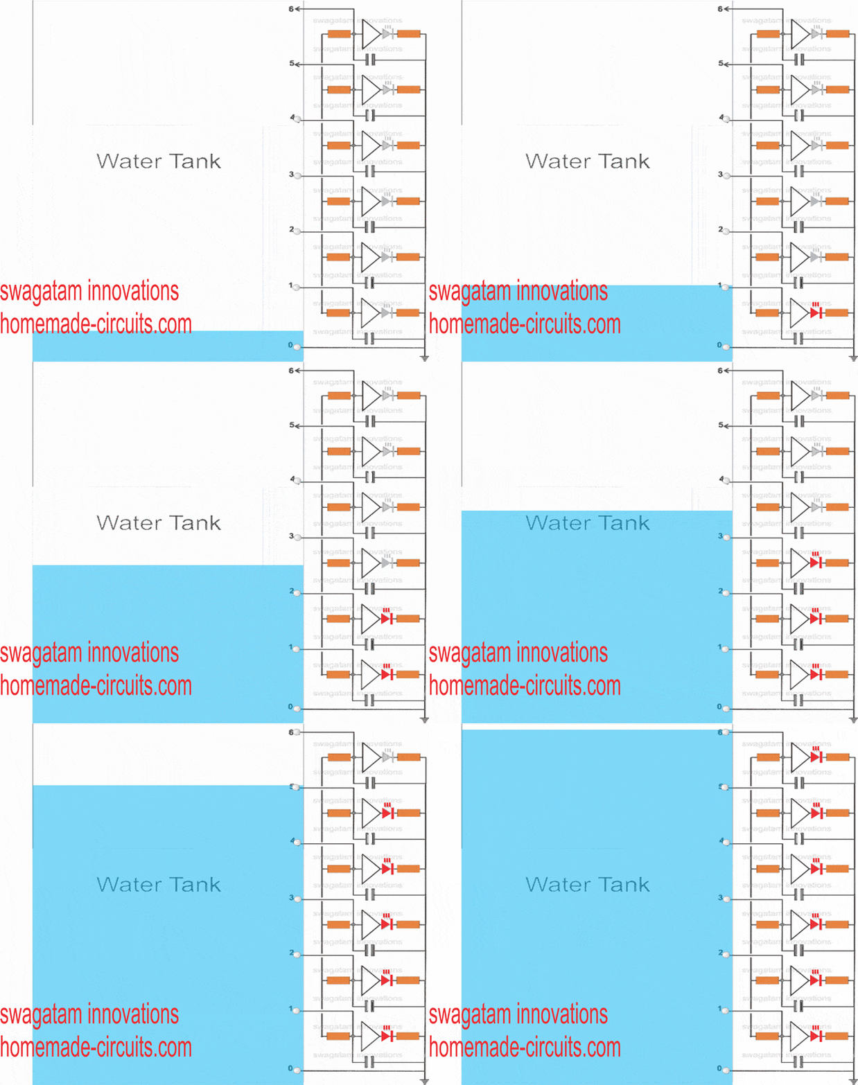
Simulation: A rough simulation of the discussed water level indicator circuit is shown below. We can see how the LEDs light up sequentially in response to the increasing water level coming in contact with the respective sensor points inside the water tank
Part List.
- All LED resistors are 470 Ohms,
- All gate input resistors are 2M2
- All capacitors are 0.1 disc ceramic.
- All the gates are CMOS NOT Gates
- All LEDs are red 5mm, or as preferred by the maker.
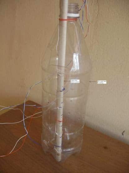
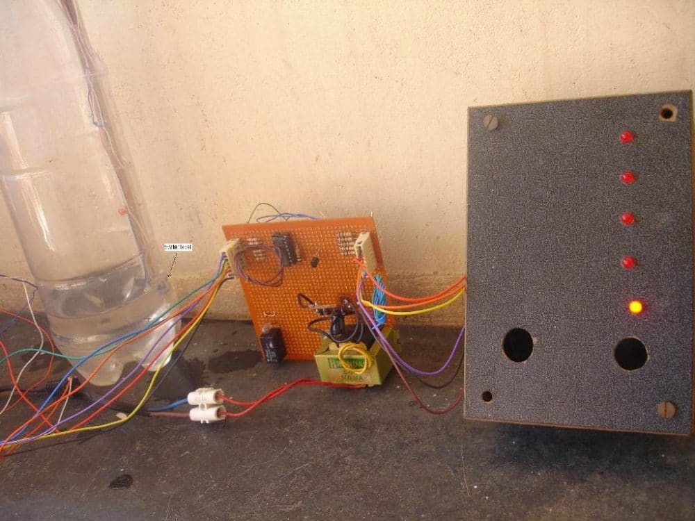
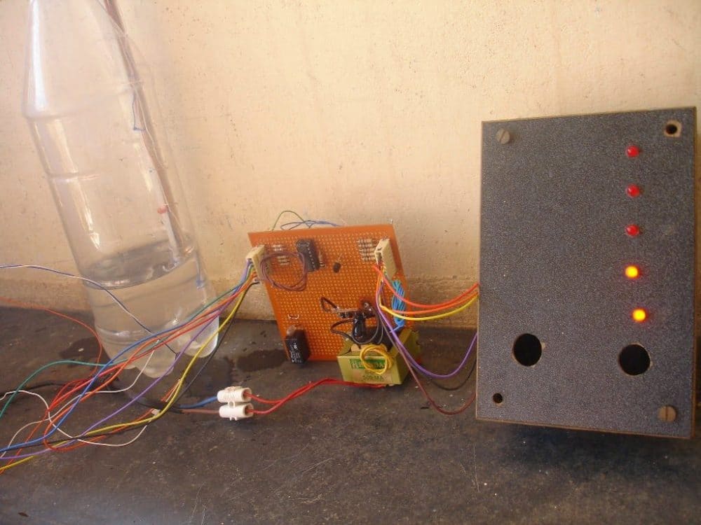
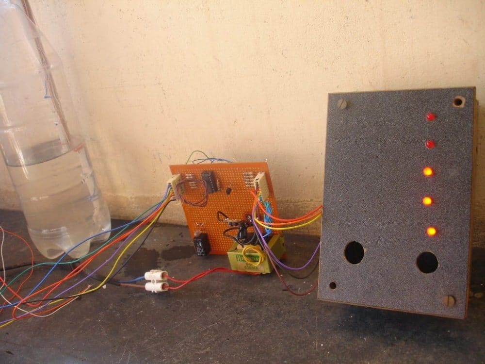
Practical Tested Prototype
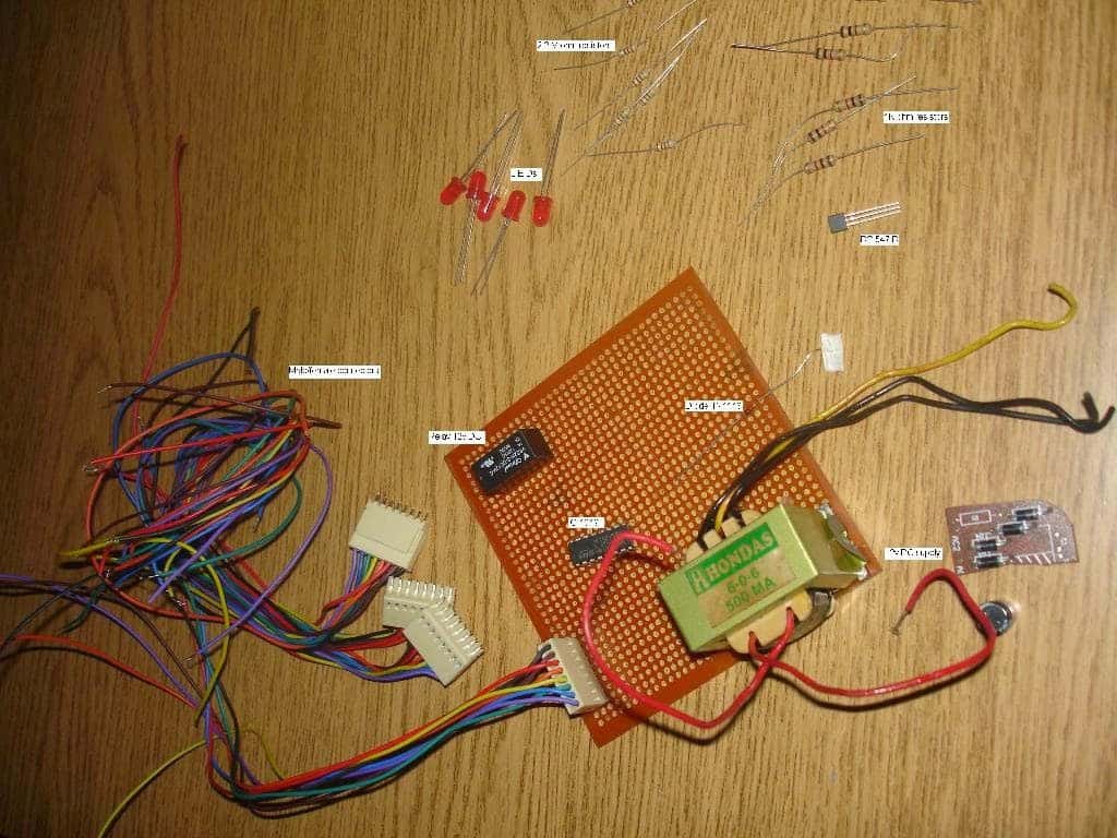
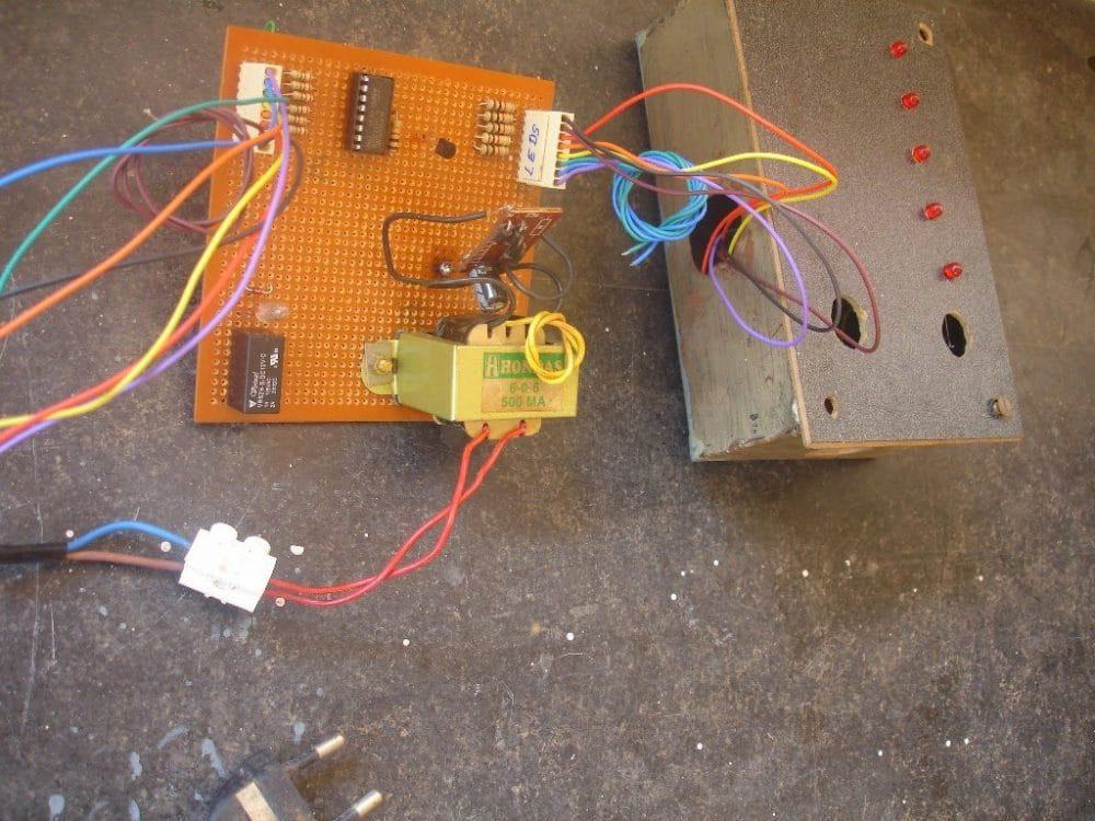
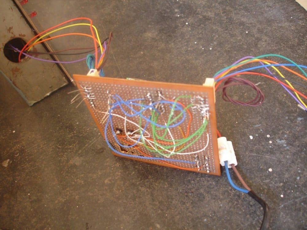
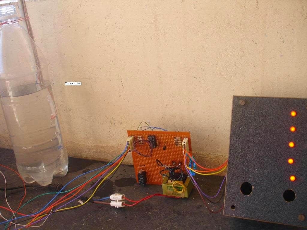
The above circuit was successfully built and tested by Mr. E.Rama Murthy who is one of the regular and dedicated readers of this blog. The following pictures of the built prototype were sent by him, let's investigate the results closely.
