Testing and troubleshooting electronic project circuits requires a multimeter, so new hobbyists may feel interested to try the following homemade multimeter circuits as their next electronic project.
Using a Single Opamp 741
The few opamp based meter circuits such as Ohmmeter, voltmeter, ammeter are discussed below using the IC 741 and just a few other passive components.
Although multimeters are available plentifully in the market today, building your own homemade multimeter can be real fun.
Moreover the attributes involved can become thoroughly useful for the future electronic circuit building and testing procedures.
DC Voltmeter Circuit using IC 741

Note: The lower end of the zero-set preset is mistakenly connected to pin#8 of the IC, please connect it to pin#1 instead.
A simple configuration for measuring DC voltages is shown above using the IC 741.
A couple of resistors Rx and Ry are introduced at the input in a potential divider mode at the non-inverting pin #3 of the IC.
The voltage to be measured is applied across the resistor R1 and ground.
Through proper selection of Rx and Ry, the range of the meter can be varied and different voltages can be measured.
AC Voltmeter Circuit using IC 741

Note: The lower end of the zero-set preset is mistakenly connected to pin#8 of the IC, please connect it to pin#1 instead.
In case you want to measure alternating voltages then the circuit illustrated above can become useful.
The wiring is similar to the above wiring, however the positions of Rx and Ry have changed and also a coupling capacitor comes into the scene at the inverting input of the IC.
Interestingly the meter here is now connected across a bridge network enabling the meter to display the relevant AC potentials correctly.
DC Ammeter Circuit using IC 741
Another circuit to measure Direct current or Amps using the IC 741 can be seen in the following figure.
The configuration looks pretty simple. Here the input is applied across the resistor Rz i.e. across the non-inverting input pin #3 of the IC and the ground.
The range of the meter can be simply varied by changing the value of the resistor Rz.

.Note: The lower end of the zero-set preset is mistakenly connected to pin#8 of the IC, please connect it to pin#1 instead.
Ohmmeter Circuit using IC 741
Resistors are one of the most important passive components which inevitably become an integral part of every electronic circuit.
A circuit may be virtually impossible to build without accompanying these amazing current controlling devices.
With so many resistors involved, a possible fault can always be on the cards.
Identifying them requires a meter – an Ohm meter. A simple design using the IC 741 is shown below just for the purpose.

Note: The lower end of the zero-set preset is mistakenly connected to pin#8 of the IC, please connect it to pin#1 instead.
Unlike most of the analogue designs which tend to have a rather non-linear behavior, the present design very efficiently tackles the problem to produce a perfectly linear response with the corresponding measurements.
The range is pretty impressive, it can measure values of resistors right from 1K up to a staggering 10 M.
You may go on to modify the circuit for enabling the measurement of more extreme values.
The range is selected by moving the rotary switch switch into the relevant positions.
How to Calibrate the Meter Circuits
Calibrating th instrument is simple and is done with the following points: Adjust the selector switch to the “10K” position.
Trim the base preset of the transistor until its emitter voltage shows exactly 1 volt (measure using a digital multimeter.) Next, Fix an accurately known 10 K resistor into the measuring slot.
Adjust the trimmer associated with the moving coil meter until the meter shows a full scale deflection.
All the circuits discussed above use dual supply voltages. The meter used is a moving coil type and is specified as 1mA FSD.
The preset across the pins 1, 4 and 5 of the IC 741 used for this homemede multimeter is used for adjusting the initial condition meter to exactly zero. Relevant Values of Rx and Ry The following are the values of the resistors required for varying the range of the respective meters.
DC Voltmeter
Rx--------------------Ry--------------------Meter FSD
10M-----------------1K--------------------1KV
10M-----------------10K-------------------100V
10M-----------------100K------------------10V
900K----------------100K------------------1V
NIL-------------------100K-----------------0.1V
DC AMMETER
Rz--------------------Meter FSD
0.1-------------------1A
1---------------------100mA
10-------------------10mA
100-----------------1mA
1K-------------------100uA
10K-----------------10uA
100K---------------1uA
AC VOLTMETER
Ry---------------------Rx-------------------Meter FSD
10K-------------------10M----------------1KV
100K-----------------10M----------------100V
1M-------------------10M-----------------10V
1M--------------------1M------------------1V
1M--------------------100K----------------100mV
1M--------------------10K------------------10mV
1M--------------------1K--------------------1mV
A request from one of the keen followers of this blog:
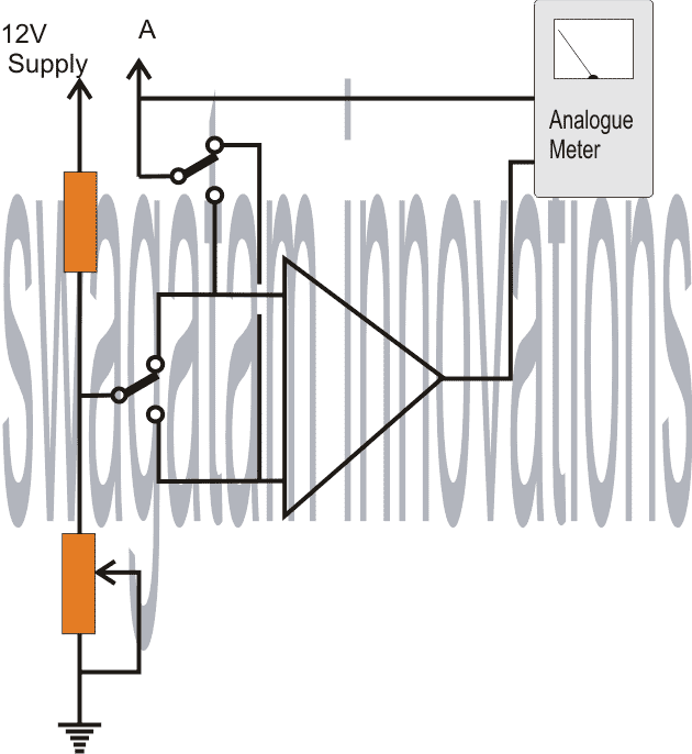
Is it possible to design a small circuit module which can be used with a multimeter to measure minimum/maximum voltage of a fluctuating signal at any point of a circuit under observation.
For example, we can switch a toggle switch in our module at MIN position and measure the voltage at point (A). The volts shown by the multimeter would be LOWEST voltage of the signal.
And when the toggle switch is positioned at MAX, and the voltage is measured again at point (A) the meter will show the HIGHEST voltage of the signal.
The Design
