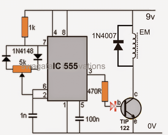
This article describes a simple circuit which can be used for pulsing an electromagnet. The IC 555 once again becomes the central part of the circuit. I have explained the making procedure of this simple adjustable electromagnet circuit for varying the magnetic power of an electromagnet.
Introduction
The circuit was requested by Mr.Jason, one of the followers of this blog. Though I'm not sure of the application needs, the circuit probably can be used for controlling the average magnetic power of an electromagnet or rather the circuit may be considered an adjustable electromagnet circuit.
The circuit involved is quite basic and has been already employed in many applications, explained in my earlier posts. Here the application is quite similar to the earlier ones, that is controlling the output load through a series of varying pulses or through PWM method.
Circuit Operation
The mark/space ratio can be appropriately adjusted using the shown configuration, which in turn can be used for varying the response of the output load.
Here the output load is an ordinary homemade electromagnet, connected via a power transistor TIP 122.
The power of the electromagnet is at the maximum level when the pot is set for achieving high mark levels than the space levels and vice versa for reducing the magnetic effects of the electromagnet.
The electromagnet may be procured ready made or can be hand made at home using suitable lengths of enameled copper wire wound over a magnetic core, like an iron nail or rod etc.
The diode connected across the electromagnet protects the transistor from back emf fluxes of the electromagnet.
The circuit may be powered with voltages between 5 and 12, but the current must be appropriately rated, otherwise the circuit will fail to operate.... if a battery is used, make sure it's rated at least at around 1 Ah.
Once powered, this adjustable electromagnet circuit will enable smooth adjustments of the attached electromagnet's magnetic field from zero to maximum.
Circuit Diagram
