Nowadays probably all of us have a spare cell phone charger lying idle in our cupboards or table drawers......so wouldn't it be a great idea if we could employ it like a super bright 1 watt LED driver and illuminate our room with white cool moon light.
Circuit Concept
As we all know that a 1 watt LED consumes about 350 mA of current and is capable of generating intense blinding white point lights. If this little high bright light source is enclosed within a reflector cabinet consisting of mirror finish lens, the light from it can be enhanced to great levels.
However a 1 watt type of LED would require a suitable constant voltage power supply for illuminating safely with the specified outputs.
Though there are a number of suitable drivers which are available in the market, a cell phone charger can be ideally used for this purpose.
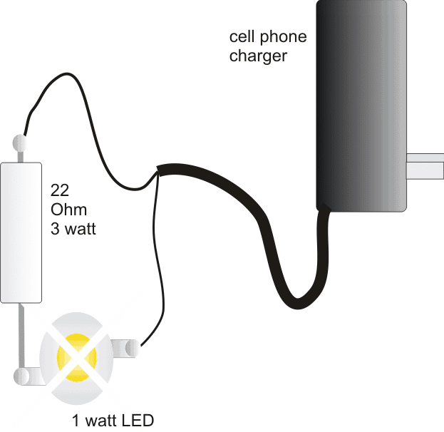
If we look at the diagram given below, we see that the whole thing can be configured using just a single current limiting resistor.

I have explained regarding the involved making procedures with the following points:
You would require a standard cell phone charger.
A 1 watt LED/350 mA white.
A 22 Ohm 3 watt resistor,
An aluminum heatsink, as specified in the given text.
Small piece of general purpose PCB, about 1 by 1 inch.
Construction Procedure:
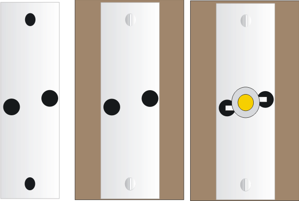
Since the LED would be generating considerable amount heat, a neatly fabricated aluminum heatsink would be required to be integrated with it so that the life and the efficiency of the device is maintained for many many years. Please see the below given diagram to know the basic heatsink design, the holes must be drilled just as soecified in the diagram and the LED leads should not touch the heatsink while it is passed through the holes and soldered over the underside PCB pads.

A small 1 mm square piece of aluminum cut into 1/2 by 1/2 inch would just suffice.
Drill the holes into the above metal, as shown in the below given diagram and fix the heatsink over the PCB using small 1/8 x1/4 screw nuts.

Next fix the LED over the heatsink in between the two center holes, and solder it leads with supporting copper wires such that it becomes locked with the underneath PCB pads. Be careful not to short the leads with the heatsink metal.
Connect the 22 Ohm resistor with one of the leads of the LED, preferably with the positive lead.
Finally, connect the cell phone charger wires to the resistor end and the other free LED end.
Make sure the polarity is correct while connecting the wires t the LED, identify them using a digital multimeter before doing the connections.
Your cell phone charger powered 1 watt LED lamp is ready, place it neatly over some corner of the room, plug it in and experience the awesome illumination, dazzling the entire premise.
Optionally the unit can be fixed inside a halogen lamp reflector for enhancing the light intensity many folds.
Making a 1 watt LED automatic emergency light circuit
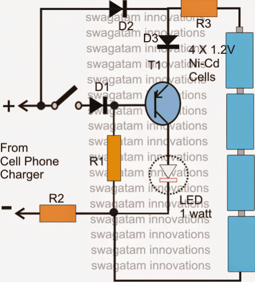
As suggested by Mr.Amit (see comment) the above concept can be very simply converted into a nice little emergency light circuit, let's see how it is done:
Referring to the figure below, assuming the voltage from the mains operated charger input to be present, and the switch in the closed position, T1 is held reverse biased so that it is unable to conduct and the LED remains switched OFF. At this position the batteries are trickle charged through R2, R3 and D2.
In case the mains fails, T1 instantly conducts and switches ON the LED automatically and vice versa.
Now suppose during the presence of mains the switch is turned of, T1 instantly switches ON, however now the LED lights up through the charger voltage (mains) while the batteries still continue to get trickle charged without getting drained through the LED.

Parts List
- R1= 100 Ohms, 1/2 watt
- R2 = 47 Ohms, 1/2 watt
- R3 = 22 Ohms, 1/2 watt
- D1,D2,D3 = 1N4007
- T1 = 8550 or 187, 2N2907
- LED = 1 watt, 350 mA, high bright
- Battery = 4 nos. Ni-Cd, AAA

