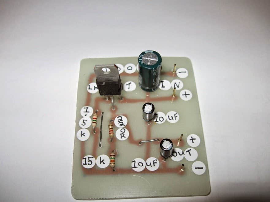
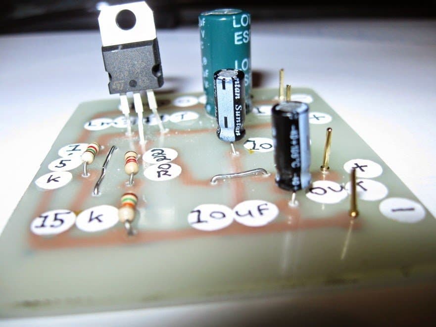
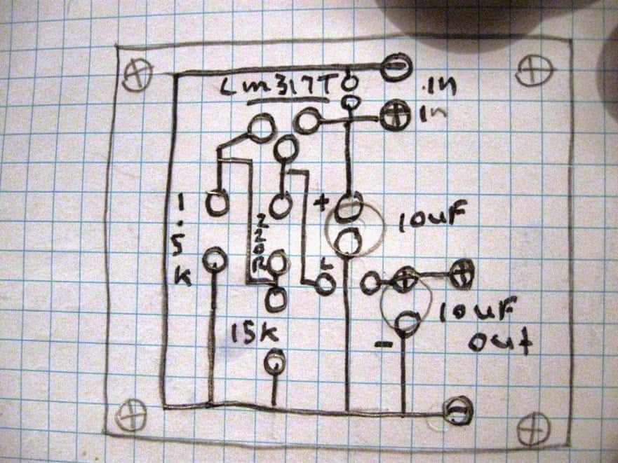
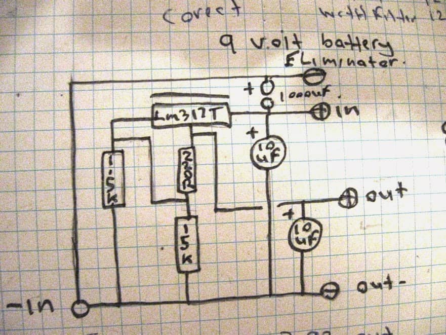
The post presents a regulated 9V battery eliminator circuit which was built and investigated by Mr. Steven Chiverton, an avid reader of this blog and an experienced electronic hobbyist. I have explained more from him.
9 volt battery eliminator circuit tests:
Circuits built 2x each circuit ive made a small modification to it buy adding a low esr 1000uf filetr capacitor between each circuits positive and negative output, latter after construction i decided to test them both but i removed the filer capacitor to note the difference between each 9 volts battery eliminator circuit.
First test was with the battery eliminator with the 1000uf low esr filter capacitor, i fed 12 volts dc into it and the output was a9.21 volts dc. Then the battery eliminator without the low esr filter capacitor was tested, i fed it the same 12 volts dc and the output was less at 9.05 volts dc.
Test 2 , i then changed the voltage output of my transformer to 9 volts dc , so i fed 9 volts dc into the battery eliminator with the 1000uf low esr filter capacitor and its output was 8.18 volts dc. Then i fed the same 9 volts dc into the battery eliminator without the 1000uf low esr filter capacitor and its output was 7.67 volts dc .
Test 3 , then i changed the transformer output voltage to 7.5 volts dc and so i fed that into the battery eliminator with the 1000 low esr capacitor and its output was ,6.75 volts dc. Then i fed the same 7.5 volts dc into the battery eliminator without the 1000 low esr filter capacitor and the output was then 6.2 volts dc .
Test 4, i then changed the transformer voltage output to 6 volts dc, and then i fed that into the battery eliminator with the 1000uf low esr filter capacitor and its voltage output was 5.30 volts dc. Then i fed the same voltage into the battery eliminator without the 1000uf low esr filter capacitor and its output was then 4.88 volts dc.
Test 5, i then changed the output voltage of the transformer to 4.5 volts dc and then i fed that into the battery eliminator with the 1000uf low esr filter capacitor and the output was then 3.92 volts dc then i fed the same voltage into the battery eliminator without the 1000uf low esr capacitor and its output was then 3.62 volts dc.
Last test test 6, i then lowered the transformer output to the last setting on 3 volts dc and fed that into the battery eliminator with the 1000uf low esr filter capacitor and its output voltage was then 2.44 volts dc . So then i fed the same 3 volts dc into the battery eliminator without the 1000uf low esr filter capacitor and its output voltage was then 2.29 volts dc .
Conclusion:
So my research tells me that the 1000uf low esr filter capacitor or any 1000uf electrolytic capacitor dose make a difference in providing better voltage output and filtering compared to not using the 1000uf electrolytic capacitor.
Circuit Diagram and Prototype


hi dada! its pritam again.. wish u happy independence day..
l u pls suggest me a low power inverter ,to drive 30watts light loads, design should be fair easy and super cheap to me..its badly needed bro… regards
hi Pritam, wish you too a happy independence day!
you can try the following circuit:
https://www.homemade-circuits.com/2012/02/how-to-make-simplest-inverter-circuit.html
nice job bro.swagatam can u help me out i have built an adjustable power supply using lm317t..used 5k pot..but the o/p varies 10v-15v..
Thanks Pritam, use a 10K pot, it'll provide a 1.25V to 20V range….but if your circuit is not showing 1.25V by varying the 5K pot, it means there's some other problem in the circuit, check it thoroughly for a possible error.