
In this article we study an RF discharge generation concept also called EMP generator capable of producing an intense RF electrical discharge in the air which may have the potentials of paralyzing and permanently damaging all electronic systems in the close vicinity. The idea was requested by Mr. Nidal.
Technical Specifications
I have seen a lot of circuits from you in your blog. I am a great fan of you!!!!
If you could help me with a circuit diagram for breaking 2.5 Volt torch bulb (Filament type) when it is switched ON and kept close to a copper pot 6 inches away (distance is between torch and copper pot) with a 12 Volt DC supply.
The thing is that, a switched on torch bulb should blow off when it is kept closer to a "copper pot" kept 6 inches apart. I hope a strong magnetic field will give the result.
But the problem is how to magnetize a copper pot to that extend?, an alternating supply give to a copper pot may develop magnetic flux around it or will it get short circuited?
Is it enough to break lamp filament? Or do I need to wind a copper coil inside that vessel to get that result?
Please help me in solving this issue.
Many thanks and expecting a reply from you soon.
Best regards,
Nidal.
The Design
The proposed concept of fusing a bulb filament through a wireless magnetic field doesn't appear to be feasible, however it could be implemented using a very strong RF discharge, such as from a very high voltage capacitor.
The idea may be carried as given in the following explanation:
A high current low voltage is first stepped up to many kilovolts, then stored inside equivalently rated high voltage capacitors and finally discharged by creating a short circuit across the high voltage capacitor leads.
The resulting discharge will generate an awesome amount RF electricity in the zone which may have the potential of fusing the filament of a bulb or illuminating a fluorescent tube momentarily.
Caution: The EMP discharge could produce devastating effects on all electronic equipment placed within the range of the discharge.
Caution: This circuit is designed to generate extremely high lethal voltages. Extreme caution and care is advised while handling this project. This project is NOT recommended for the newcomers.
Circuit Diagram
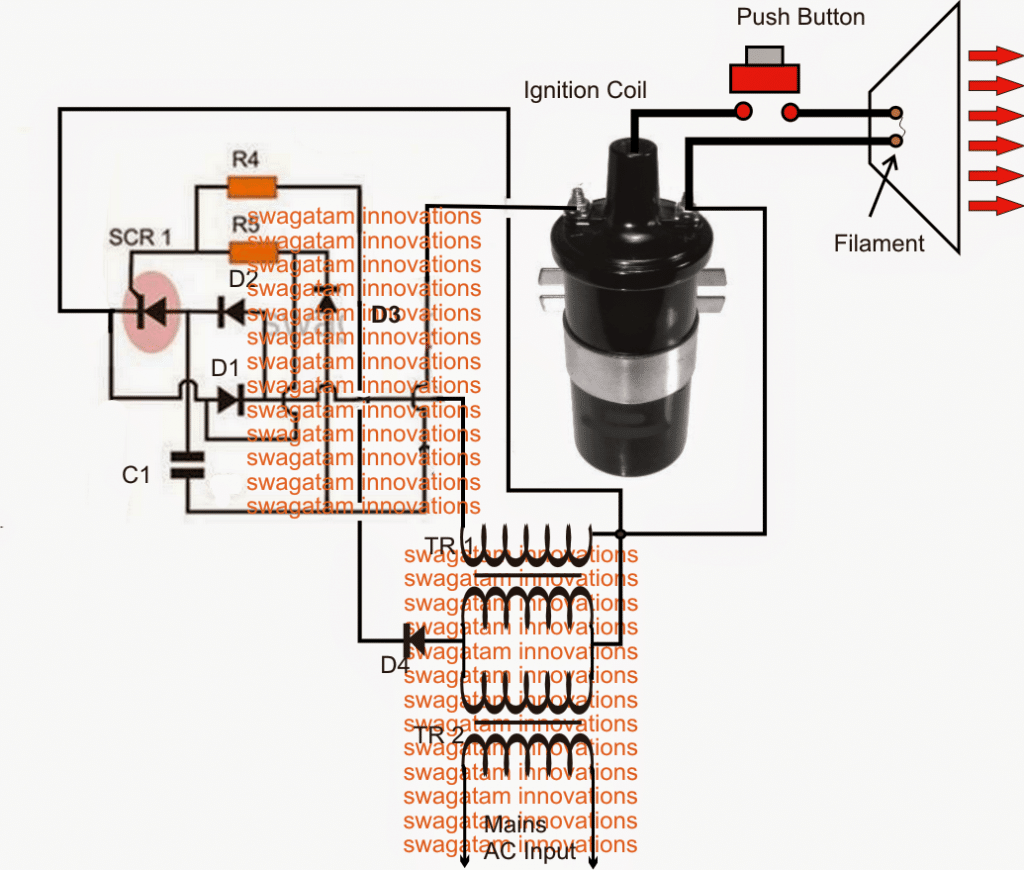
How it Works
Referring to the diagram above, the set up shows a basic capacitive discharge system. The circuit comprising the diodes, C1 and the SCR form a capacitor charge/discharge switching stage which is powered from a boosted AC using a couple of mains transformers.
TR1/ and TR2 transformers are coupled together such that the low voltage TR2 winding connects with the TR1's low voltage winding.
When mains is applied to TR2 primary, an equivalent 220V (low current) is induced across the upper winding of TR1.
This voltage is used for charging the high voltage capacitor C1 in the circuit via a switching SCR stage which is triggered through the 50Hz low voltage input from TR2 via D2.
The switched C1 discharge is applied to the primary of a car ignition coil, which steps up this voltage to a staggering 40,000V or higher.
This voltage is kept hanging across a thin filament position within a suitably dimensioned conical shaped aluminum radiator.
When the shown push button is pressed, the high voltage tries to force its path through the filament creating a massive arc and explosion across the points.
This generates an intense RF disturbance in the region which is further magnified and propagated by the cone to the target which is here a small electrical bulb.
If the discharge is sufficiently strong may produce a momentary illumination of the bulb filament and then fusing due to the generated RF electricity.
Parts List
- R4,R5 = 100 OHMS, 1 WATT
- D1, D2, D3, D4 = 1N4007
- C1 = 100uF/500V,
- SCR = BT151
- TR1/TR2 = 220V/0-12V/1AMP TRANSFORMERS.