The low resistance measuring circuit I have explained below can be used for measuring all milliohm resistances below 1 ohm with extreme accuracy. The resistance to be measured can be as low as 0.01 ohm or 10 milliohm.
The output of the circuit converts the resistance value to exactly equivalent volts, which means the output of the circuit could be hooked up with DMM voltmeter range for getting the low resistance values in terms of voltage with extreme precision.
Accuracy and Resolution
The majority of digital multimeters might correctly measure resistance values as low as five ohms only.
Below 5 ohms, you immediately start facing the digital multimeter resolution issues and start seeing resistance values that are rubbish.
We say rubbish, because of the following reason: Normally, when we try measuring a 0.1 ohm resistance value on a digital multimeter, we need to rotate the selector switch to the meter's lowest range (which can be usually the 200 ohm range).
For almost all standard DMM's, the resolution specs is provided as ±1 digit. Put simply, when the meter display shows 0.1 ohm or 100 milliohm, the true resistance value may be anywhere from 0 to 0.3 ohm. This equals to an accuracy of ±100%, which is not really very helpful for the majority of applications.
Likewise, in case you try measuring a 1 ohm resistor over a 200 ohm range of a DMM, the most accurate results that you may anticipate is a measurement display of 1.0 ±1 digit; That means, the most effective accuracy is ±10%.
Therefore, the meter resolution significantly decreases the reliability of the measurement, although you may find most DMM's are accurate within ±1% only if we measure any parameter that may be higher than lowest available meter range.
However you will find numerous scenarios where measuring low-ohm resistance precisely becomes crucial.
These may include evaluating meter shunt resistances, building loudspeaker crossover networks and amplifier output stages, and testing or repairing power supplies or any some other circuitry which involve serious use of low value resistors.
The circuit for measuring low value resistance below 1 ohms presented below eliminates the resolution limitations of the standard DMMs. You are able to plug in the circuit directly to the probe slots of the DMM and measure small value resistances as low as 0.01 Ohms or 10 milliohms.
However, the low resistance measuring circuit has one limitation. As the resistance value to be measured decreases below 10 milliohms, issues due to contact resistance of the probes, and connecting wire resistances wires starts developing causing discrepancies in the end result.
Circuit Description
The low ohm measuring circuit as indicated in diagram below includes a 5 volt regulator stage, a constant-current source stage using diodes D, D2, and transistor Q1, and an op amp gain control stage (U1).

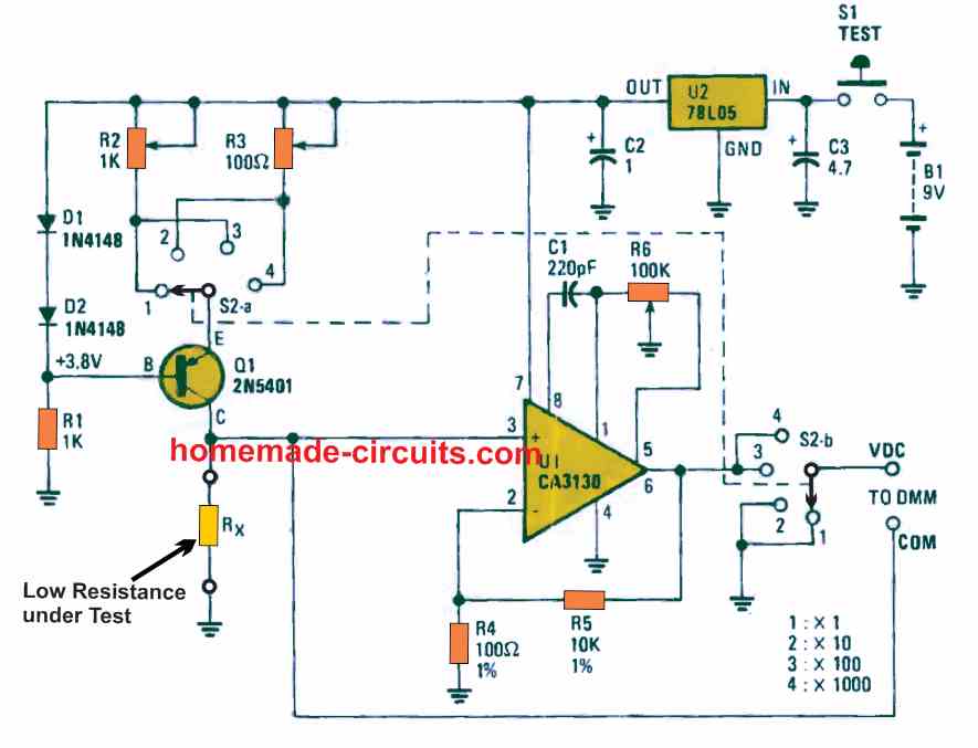
The circuit is powered from a 9 V PP3 battery. This 9 V output is regulated to +5 volts (DC) by a 78L05 regulator. The regulation enables a stabilized power supply for the constant current source stage and the opamp.
The balance of the circuit only gets linked with the battery as soon as test-switch S1 is pressed. The current is used from the battery only during the time the resistance measurement is being tested, which ensures a prolonged battery life.
Constant-current source stage is built using the parts D1, D2, and transistor Q1 along with a 1k resistor R1.
Transistor Q1 is configured in the form of an emitter-follower stage. Its emitter side terminal follows the voltage applied to its base, with a reduction of around 0.6 volt due to the inherent base-emitter voltage drop.
The Series diodes D1 and D2 maintain the Q1 base at a constant 1.2 volts below the +5 V DC supply line. This ensures that the Q1 emitter is constantly 0.6 volt lower than the + 5 DC line. Resistor R1 fixes the current at 5 mA via the two diodes D1 and D2.
This 0.6 V DC generated across one of the multi-turn trimmer potentiometers, R2 or R3, as per the selection by the switch S2-a. The 0.6 V fixes the current by means of Q1 and the resistor under test, Rx.
In case R2 is selected, the test current becomes 1 mA; with the selection of R3, the test current turns into 10 mA. Across the a pair of ranges (x 1 and 10) at the bottom, the voltage across the resistance under test, Rx, is executed right to the DMM terminals through the banana plugs.
On thecouple of ranges from the top, the op-amp gain stage (U1) gets switched ON enabling the DMM to read the voltage across the opamp output (pin 6) and provide the measured date for the test resistor, Rx.
The op amp U1, is configured in the form of a non-inverting op amp stage having a constant gain of 1 + 10,000/100 = 101. Since we would like to have a gain of exactly 100, we determine the voltage between the op amp output and the voltage across Rx.
Therefore, if switch S2 is moved to the position 3 (x 100), the current established through the constant-current source turns 1 mA; the multiplying element for Rx will be x100. When S2 is turned to the position 4 (x1000), the current will be 10 mA and the multiplying aspect will be 100 x 10 = 1000.
Multi-turn trimmer-potentiometer R6 modifies the offset parameter of the op-amp to ensure that, when there's zero voltage across Rx (meaning, when the measurement probes are short circuited), the output also turns to zero.
Enclosure
The complete circuit milliohm meter circuit can be enclosed inside a tiny plastic box. On the box's front panel can be a couple of multi-way binding post terminals fixed, on which the resistor to be measured (Rx) could be hooked up.
Additionally there will be a rotary switch with 4-way range (x1, x10, x100, and x1000) as well as a TEST push-button.
A pair of banana plugs may be used protruding out at a right angle from the backside of the box; which may be positioned some distance apart so that it allows the entire low resistance circuit to be easily plugged-in into practically any standard digital multimeter or DMM terminal holes.
The low resistance measuring circuit's output generates a voltage which is directly equivalent to the low resistance that is measured.
Practically, the circuit is calibrated to ensure that 1 ohm generates an output of 1 millivolt multiplied by the calibration provided on the the range-switch setting.
For instance, on the x1000 range, 1 ohm would be corresponding to 1 mV x 1000 = 1 volt. On the x10 range, 1 ohm would be similar to 10 mV, and so on.
How to Calibrate
Switch on power supply by pushing button S1. Verify that the regulator (U2) produces the required +5V at its output, and about 3.8 V DC is produced across the 1K resistor (R1) in series with diodes D1 and D2.
Next, hook up your DMM across the Rx test terminals and set it to the DC 2mA scale. Adjust the switch S2 to the x1 position and set R2 for getting a display of 1 mA.
Once these are accomplished, adjust the DMM to the DC 20 mA scale, set up S2 to the x10 position and adjust R3 to get a reading display of 10mA.
After these steps the calibration could be accomplished by fine-tuning the offset voltage. To get this done, remove the meter from the above discussed position, and set it up to the DC 200 mV range.
After doing this, adjust S2 switch of the circuit to the x100 position, short circuit the Rx terminals with a copper wire, and next push the banana plugs of our Low Ohms measuring circuit into the COM and VDC terminal inputs of your DMM.
Start rotating the potentiometer R6 for ensuring a starting reading of slightly above 0 mV on the DMM display….immediately after this rotate the R6 back to get a reading of exactly 0 mV on the DMM display.
This finishes the calibration procedure.
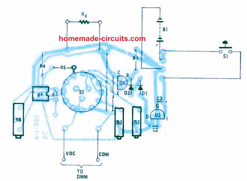
PCB Design

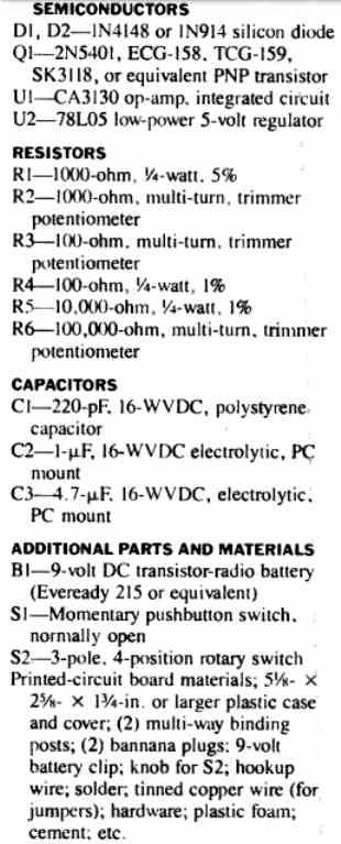
Parts List
Another Simple Milliohm Tester Circuit
I wanted a milliohm tester circuit that could be used to measure resistance on printed circuit boards to track down shorted components. I looked at several designs and combined several ideas into this project.
By Henry Bowman
Circuit Operation
Referring to the schematic, the milliohm tester is powered by two 9 volt dry cells. The power is connected to the circuit by a double pole, single throw switch S1. Since the voltage was pure dc, I did not add filter capacitors. I didn't add a led to indicate power on because the meter will move to the right as soon as power is applied.
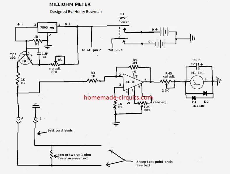
The 7805 regulator and R1 provide a constant current and voltage at the base of Q1. Some designs use a zener diode for this function, but the 7805 does a great job also. The larger voltage +9 is in series with RH1 to the emitter and the voltage at the base appears negative to the emitter, allowing emitter, base, collector current flow. RH1 provides for adjustment of the current in milliamps through Q1 & R2 to test lead A.
The current will not exceed the constant current at the base of Q1. R2 was also added to the collector side to provide some temperature compensation for Q1. When a resistance load is connected to the test lead terminals A&B, the voltage at terminal A is connected to R3 and the input pin 2 of the 741 IC.
The combination of R3 and R4 determine the voltage gain of the opamp ( R4/R3=1000). Pin 2 of the opamp is the inverting input, so the output at pin 6 is negative.
RH2 provides for zeroing the meter to the left side. The negative voltage is passed through RH3 to the 1 ma full scale analog meter. RH3 provides for calibrating the meter to the right side (full scale). D1 & D2 offer some over voltage protection. C2 is optional.
I added C2 to slow down my meter movement. As the resistance is lowered across test points A & B, the voltage will also be lowered to the input of the opamp. The meter operates just opposite of an analog ohm meter.
With only the ten 1 ohm resistors in parallel across the test leads, the meter will be at full scale to the right, indicating 0.1 ohm.
When a zero ohm resistance is connected to the test leads, the meter will move to the extreme left for zero ohms. If you want more sensitivity to resistance, increase the parallel one ohm resistors from ten to twelve. This will make the full scale resistance .08 ohms instead of .1.
Construction Details
You need the largest 1mA, or 750uA meter, that you can find. I found one from an old automotive engine analyzer that was 5-3/4” wide and 4-1/4” tall (14.6 X 10.8CM). It has a large spread from full scale to zero. Resistors can be 1/8, or ¼ watt due to the low current.
Components can be mounted on a universal type pc board or use point to point wiring on a perforated board. I used sockets for the transistor and ic, which make them easier to replace. “Dead Bug” wiring can also be used, where the ic is placed upside down on the board and wires soldered directly to the ic pins.
If you solder the ic and transistor, be sure to grip each lead with needle nose pliers to provide a heat sink for the pins. Be sure that you place the negative side of the meter to the RH3 potentiometer.
The postive side of the meter connects to ground. RH1 and RH3 pots need their center connection pin strapped to the right pin. The potentiometer connections are viewed with the pot shaft facing you.
RH2 has wires connected to all three connections. I cannot over emphasize the need for perfect soldered joints in this project.
The tester is very sensitive to very small changes in resistance. The three potentiometers and power switch should be mounted externally with the meter. Provide a two terminal mounting post for the test leads A & B and the two connecting wires from the pc board.
Provide some additional strain relief for the test cords by using a cable tie or cable clamp to secure the ends inside the enclosure.
The test leads should be insulated copper stranded wires and sized #12--#14 gauge. I used a piece of power cord from an old electric saw.
The soldering must thorougly melt on the test leads to assure a good connection. Test leads should extend 16” (41CM) from the chassis. Install the ten (or 12) 1 ohm resistors on the test leads about 8” (20CM) from the chassis.
The number of resistors you choose depends upon the full scale reading your require. Ten will provide a 0.1 ohm full scale and 12 will provide .08 ohm full scale. The resistors can be 1/4 or 1/8 watt rated. The resistors can be pigtailed together and each side soldered before placing on the test leads.
Again, be sure you have a hot iron and good solder flow on the resistor leads to the copper wires on the test leads. Don't insulate the resistors until you have calibrated the tester and are satisfied that your solder connections are good.
Once you have completed installing resistors, move to the very end of the test leads. Strip off about a 1/2” (1.3CM) of insulation off each of the test lead ends. Once ready to power on, go to Calibration and follow step-by-step to avoid damage to the meter.
Calibration
It is assumed here that you have the 1 ohm resistors connected to the test leads and the ends have been stripped. Be sure you have allowed enough time for the resistors to cool down from the soldering. Take the two bare ends of the test leads and twist them together to short.
Before powering up, set the zero adj. and cal adj. potentiometers to mid range. Set the ma adj. potentiometer to fully clockwise position.
Remember before you power up that zero ohms is to the left and 0.1 (or 0.08) is to the right. Switch on the power to the tester and observe the meter. If it deflects to the left, below zero ohms, adjust the zero pot clockwise until the pointer is on zero.
If it went to the right, of zero, adjust the zero pot counter-clockwise until it is on the zero. Remove the shorted ends and the meter should move to the right side. You will have to adjust the Cal pot to get the meter to the right side full scale.
Now place the short back on the leads and see if additional zero adjustment is required. If you had to readjust zero again, remove the short again and readjust the cal pot. Repeat this until shorting and removing the short requires no further adjustment. Now you have the calibration in the ball park.
Construction after pre-calibration
Now that you have the pre-calibration completed, you need to add some sharp pointed metal ends to the test leads. These can be sharpened copper nails, or sharp test probe ends removed from junk equipment.
These sharpened ends should be about an inch (2.5CM) in length. The stranded copper on the test lead ends should be wrapped and soldered around the opposite end of the metal pins. Again, the solder must melt thoroughly so that it adheres to the stranded copper and pins.
You will need to provide shrink tubing, or tape, over the soldered ends of the test pins. Since we've now added the resistance of the pins, we need to recalibrate once again. You will need to use a good conductive surface to place the pins on to calibrate.
You can use a printed circuit solder run, a copper coin, or several layers of tin foil for the conductor. Try to avoid touching the pins while testing as small ac voltages from your skin contact could effect meter readings. Place the test pins as close together as possible on the conductor.
Turn the power on to the tester and adjust the zero pot until it registers zero ohms (on left side). Some pressure may be required on the test pins to get zero ohms. Remove the pins from the conductor and check the meter needle for full scale to the right. If the cal pot requires adjustment, you'll have to repeat the short on the conductor again and recheck zero.
Calibration will be completed when no adjustment is required by shorting, or removing the short. There should be no movement of the meter pointer when the test wires are wiggled or moved around.
If you have this problem, it is due to a bad solder connection. Reheat all soldered joints on the test leads, mid point resistors , points A & B and the problem should be corrected.
Some type of insulation can now be installed on the test cord resistors. Now you will need to mark your meter face plate with as many graduations as possible.
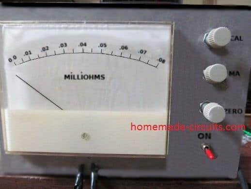
For a .1 full scale, ¾ scale is .075, mid scale is .05, ¼ scale is .025. If you have room on your meter to provide 1/8 scale, it will be .012 ohm. With my meter being so large, I was able to use 12 resistors and .08 as full scale, .04 half scale, .02 as ¼ scale and .01 as 1/8 scale .
How to Test
To test resistance with this milliohm meter circuit, I took a 2” (5CM) length of solder and flattened the ends with pliers.
I placed the test probes in each end and the meter pointer was halfway between zero and .01 and measured .005 ohms. With my tester, I can detect resistance down to .002-.003 ohms.
Now you're ready to run down shorts on printed circuit boards on various electronic items. I was able to narrow down a power board short to two surface mounted power transistors that were mounted side by side.
There were several components that could have been the problem, but through resistance testing, I narrowed the problem down to two components.
I clipped the emitter on one and the short remained, clipped the emitter on the second one and the short went away.
Before each use, power up and let the tester warm up for a few minutes. Make a quick check of full scale and zero ohms calibration and you're ready to trouble shoot. The current drain on the +9 is about 30ma. The current drain on the -9 is 2-3 ma.
Prototype Image
You need very badly to zero the meter shown in your last photo.
Also… why would you not use an LM723 (or similar) as a high-accuracy constant-current source? That would simply the circuit considerably.
And… why in the world would you draw a 7805 BACKWARD in your last schematic? Just as a MOSFET or bipolar transistor should always be drawn in the “correct” orientation, a linear voltage regulator should always be shown with the input on the left and the output on the right. If you draw it any other way, your audience will absolutely try to build their circuit backwards and pester you with “Why doesn’t my circuit work? And who’s going to pay for the fire on my benchtop?”.
Dear sir,
Can you provide a circuit diagram of an adjustable (cv,cc)linear dc power supply using lm324 and 2n3055 transistor
output : 0-24v
current: 0-25amp
with cv and cc
Hello Brij,
you can try the following circuit:
https://www.homemade-circuits.com/universal-variable-power-supply-circuit/