
A microamp meter or microammeter is a device that allows the user to measure extremely small current levels, in microamps, which is normally not possible to measure using conventional multimeters.
A conventional panel meter or multimeter will not be able to properly measure currents of a few microamps or less. It is required to utilize an active circuit, such as the one illustrated below, to perform meaningful tests.
It can be employed as a stand-alone device or as part of a larger device that requires a very sensitive current meter.
How the Circuit Works
The sensitivity is in 6 ranges, ranging from 100 nA to 10 mA, with the higher levels provided to enable calibration and as most multimeters have hardly any low current ranges.
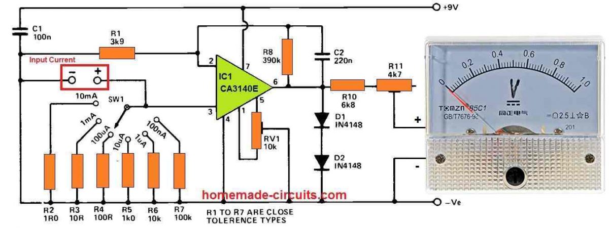
R10 and R11 are used for implementing a 1V FSD voltmeter with the meter M1. The latter is tweaked to get the meter's sensitivity exactly right. IC1 is an op amp with a DC voltage gain of roughly 100 times and is wired in the non-inverting configuration (using the feedback network R8-R1).
In order to increase stability and immunity to stray interference pick-up, C2 is used which minimizes the AC gain to around unity.
SW1 selects one of the range resistors between R2 and R7 to bias the non-inverting input of IC1 to the 0V rail. In principle, this results in zero output voltage and no meter displacement, although in real life testing, tiny offset voltages must still be compensated by utilising offset null control, RV1.
When the microamp meter circuit receives an input current, a voltage is generated across the specified range resistor, which is amplified to create a positive meter deflection.
As an example, when R2 is toggled into the circuit, 10 mA is required to achieve full scale deflection since 10 mA causes 10 mV to be generated across R2. IC1 will amplify this one hundred times, yielding one volt at the output.
The range resistor is increased by a factor of ten for creating most useful ranges, lowering the necessary current at the input, to produce 10 mV and achieve full scale deflection on meter M1.
This arrangement demands a high input impedance in order for the amplifier to not waste any significant amount of input current, which is done by employing a FET input op amp having a standard input resistance of 1.5 million meg ohms.
D1 and D2 limit the output voltage of IC1 from reaching around 1.3 volts, therefore protecting M1 from over-loads.
How to Set up
To set up the microamp metre circuit, begin adjusting RV1's slider near the pin 5 side of its rotation (you might find a substantial deflection of M1), and then pull it off just far enough to bring the meter needle to the zero mark, but no farther than that.
Picoammeter Circuit
The next circuit below can measure current even lower than microamps, down to picoamps.
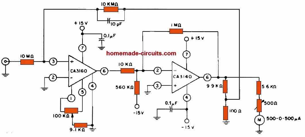
CA3160 and CA3140 BiMOS op amps are used in this circuit to generate a full-scale metre reading at current levels that's as low as 3 pA. The CA3140 acts as an x100 gain stage, providing the metre and feedback circuit with the needed positive and negative output range. The CA3160's terminals 2 and 4 are at zero voltage, therefore its input is in "protected condition."