
A transceiver is a wireless communication device which has its own transmitter and receiver units built-in for communicating with another similar device at some distant location. The user on both sides with the unit has to switch from transmitter to receiver and vice versa while speaking and hearing to each others conversation respectively.

Introduction
In this post I have explained a simple low range transceiver circuit, which could be used by any hobbyists for having fun while talking to neighborhood friends without incurring any cost.
Additionally, this mobile broadcast band transceiver can provide your home a cheap wireless intercom system, enabling you to talk to another identically prepared device. It can be used in vehicles during a journey along with friends, and may also be helpful for normal field and camping out application.
Construction Hints
All terminals of the parts must be kept as short as possible while assembling the unit. The complete could be assembled over a section of veroboard or an appropriately drilled plastic board, sized to adjust within the enclosure.
The transceiver can housed inside a 3-1/2 in. x 2-1/8 in. x 2 in. aluminum box with all the parts assembled over a compact PCB or a veroboard. Keep all component leads short.
Inductors L1 and L4 are Bourns, 15 µh, subminiature, RF chokes.
L2 and L3 are Bourns, 1.2 µh , subminiature, RF chokes. S1 is a DPDT mini toggle switch. J1 is a banana jack for the antenna.
The antenna can be less than 5 feet in long, which could be a normal telescopic antenna readily available from the market.
Using an Electret MIC
In the original design the mike was a carbon type, having an impedance of 1.5K, connected between the joint of R1/C3 link and S1. Since a carbon mike is obsolete nowadays, I have replaced it with an electret mic circuit.
The earphone can be a normal 1K magnetic type or a standard headphone, plugged into connector J2, which is a miniature phone jack.
Using 3rd Overtone Crystal
The crystals used in this transceiver unit is a 3rd overtone type. Meaning, the fundamental frequency of the crystal can be any value, but it must be specified with a 3rd overtone feature.
For example, if the fundamental frequency of the crystal is 27 MHz, then the crystal will be oscillated at a 3rd overtone frequency of 27 x 3 = 81 MHz approximately.
How the Circuit Works
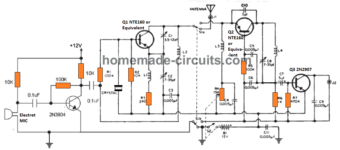
The transistor Q1, along with the crystal, the capacitors C1, C2, C3, and inductor L2 forms a high frequency RF oscillator, whose frequency is determined by the 3rd overtone value of the crystal. Since a crystal is used the frequency is stable without variations.
The Q2 transistor along with C8, L4 also forms an oscillator but is designed to work as the receiver circuit. C8, L4 must be tuned precisely to lock on the frequency of the crystal from the other transceiver unit.
The switch S1a/S1b is a ganged selector switch for selecting between transmitter and receiver function in tandem. When the switch is turned towards Q1, it activates the transmitter so that the transmitted signal is transmitter through the antenna.
When the switch is towards the Q2 side, it activates the receiver section so that it can receive the signals transmitted from the other distant transceiver.
The Q3 section is a simple audio amplifier which amplifies the captured signals from Q2 to suitable levels for the headphone.
The MIC section is a single transistor mic amplifier which amplifies the voice signals and modulates the Q1 frequency for the intended transmission of the voice signals into the air.
S2 is an ON/OFF power switch which could be integrated with the pot R4. R4 is a sensitivity control circuit which can be used like a volume control also.
The battery can be a 12 V sealed battery or a Li-Ion battery.
How to Set Up
The set up procedure is actually easy. To get an optimal range from the unit, peak the resonance of the transmitter by adjusting the two variable trimmers C1, C2 until the maximum strength is detected. This could be simply accomplished with the help of a field strength meter or S-meter.
Parts List
| Component | Value/Specification |
|---|---|
| Transistors | Q1, Q2: 2N741 |
| Q3: 2N1192 | |
| Resistors (Ω) | R1, R5: 100K |
| R2: 10K | |
| R3: 240 | |
| R4: 15K (potentiometer with switch) | |
| R6: 1K | |
| R7: 470K | |
| Capacitors (µF) | C1: 3.5–12 pF (variable) |
| C2, C8: 7–35 pF (variable) | |
| C3, C4, C5, C6, C9, C11: 0.005 | |
| C7: 5 | |
| C10: 5 pF | |
| Inductors | L1, L4: 15 µH (subminiature RF chokes, Bourns or similar) |
| L2, L3: 1.2 µH (subminiature RF chokes, Bourns or similar) | |
| Miscellaneous | Microphone: Carbon, 1.5K |
| Earphone: Magnetic, 1K | |
| Crystal: 3rd overtone in miniature holder | |
| Antenna: See text | |
| S1: DPDT mini toggle switch with spring return | |
| S2: Part of R4 | |
| J1: Banana jack | |
| J2: Miniature phone jack | |
| B1: 12 volts |
FCC Guidelines
Warning: This unit can be categorized under Part 15 of the FCC's rules. You must not build and use this transceiver circuit unless the certification card (or reasonable facsimile; see page 32) is signed by an authority having at least a Second-Class Radiotelephone Operator License, and only after a thorough verification from the authority.
Another Simple Transceiver Design
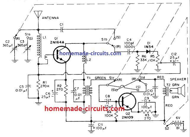
Referring to the circuit diagram above, C1 is simply a so called "gimmick" capacitor, which is normally made up of two pieces of loosely twisted hook-up wires, one terminating from S1a and the other from S1b. Make sure not to remove the enamel coating of the wire.
LI is an ordinary ferrite loop antenna which are commonly used in AM radio receivers. The following image shows a standard AM loopstick antenna coil.
How to Make the Antenna Coil
L1 antenna coil is made using 73 turns of 0.3 mm super enameled copper wire over any standard ferrite rod. The transistor base side of L1 consists of 10 turns over the 73 turns, using the same wire.
L2 is made by winding a 25 feet of No. 7/41 litz wire over a 3/4 -inch long and 1/2 inch diameter ferrite core. T1 is a 10K to 2K miniature driver transformer. T2 is a 2K to 100 -ohm miniature output transformer.
T1, T2 are standard audio output type transformers.
The loud speaker can be a small 8 ohm 1/2 watt speaker. S1 is a four pole double throw switch with return lever action. S2 is an integral part of a 10K volume control with switch.
The antenna is simply a long telescopic antenna (not to exceed 7 feet), which could be a normal car radio antenna.
How to Operate
To operate the simple transciever circuit, turn on the volume control/switch and adjust the knob for maximum volume. Also tweak C2 trimmer until you hear a null point on any AM broadcast band receiver channel.
You will need to build two of these units which must identical with their settings and then enjoy communicating across a distance a 100 meters ro even more depending on the antenna orientation.
Setting Up
When testing the transmission frequency adjust the gang capacitor C3 for maximum power. If you happen to hear a lot of squealing, you may have to adjust the twisting length of the "gimmick" capacitor to reduce the sensitivity of the transceiver and the squealing effect.
Make sure the transmitting frequency and the receiving frequencies are different across the two communicating transceivers, this is to ensure minimum feedback effect and disturbance.
Parts List
| Component | Value/Specification |
|---|---|
| Transistors | Q1: 2N164A |
| Q2: 2N109 | |
| Resistors (Ω) | R1: 270K |
| R2, R3: 270 | |
| R4: 100K | |
| R5: 10K (miniature, with switch) | |
| R6: 33K | |
| Capacitors (µF) | C1: See text |
| C2: 365 pF (variable) | |
| C3: 365 pF (variable) | |
| C4: 100 pF, 1000V | |
| C5, C7, C10: 0.01 | |
| C6, C8, C12: 25 | |
| C9, C11: 100 | |
| Diode | D1: 1N34 |
| Inductors | L1: Ferrite loop antenna |
| L2: 25 ft. No. 7/41 Litz wire on 1/2 in. D. ferrite core, 3/4 in. length | |
| Transformers | T1: 10K to 2K miniature driver transformer |
| T2: 2K to 100-ohm miniature output transformer | |
| Speaker | 10-ohm, 2-1/2 in. |
| Switches | S1: 4PDT (return lever) |
| S2: On R5 | |
| Battery | B1: 6 volts |
| Antenna | See text |