

In this article we will explore 3 different Morse code practice oscillator circuits, for generating exact replication of Morse code signals in the form of dots and dashes. Contributed By: Anil Patil
What is Morse Code
Morse code is a legacy method of message encoding that uses rhythm and impulses to transmit telegraphic communication.
Morse code employs dots and dashes to depict a particular message's alphabetic letters, numerals, punctuation, and special characters in written communication.
Dots are generated in the form of brief beeps, clicks, or light flashes for communicating a message by sound, radio waves, or light bursts, whereas dashes are longer.
A scientist named Samuel Morse basically created the Morse code, and hence the name Morse code. Compared to the 19th and 20th centuries, it is no longer used as frequently nowadays.
Morse code was eventually superseded by teletypewriters, which were created in the early 20th century and had their own codes.
Gradually, other forms of technology that are easy to utilize for communication started getting increasingly prevalent.
These days, it's simple to create Morse codes using a smartphone app or a web tool that accepts text as input and returns the code as copyable text or downloadable audio.
Its use as a means of transmitting encrypted communications has been rendered obsolete in favor of stronger encryption methods made available by cutting-edge contemporary computer systems.
What is Code Practice Oscillator
Code practice oscillator is an electronic oscillator circuit that can be used for generating sound signals resembling the Morse code dots and dashes.
Today DIY code practice oscillator circuits can be built at home for practicing the creation of Morse code sound signals of dots and dashes, simply by operating a press button or a touch pad.
Practical Circuits
The following section of the article explains a few simple code practice oscillator circuits which can be used for generating audible sounds similar to the Morse code dots and dashes.
Using IC 4093

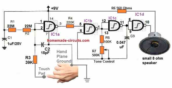
The figure above depicts a touch-activated coding practice oscillator circuit. Here, IC1, a single 4093 quad 2-input NAND-gate Schmitt-trigger, handles all of the requirements of the code practice oscillator.
Using a couple of 22M resistors (R1 and R2), the gates of IC1a are biased high.
This holds its output in the low state. An audio oscillator circuit can be seen configured using IC1b and IC1c.
This oscillator activates only during the time pin#5 of IC1b is high. The 4093's fourth gate, IC1d, is configured as a buffer gate. It operates the speaker and gives isolation to the oscillator circuit.
The input gate voltage of IC1a is decreased to almost zero when the key touch pad and ground base are touched together, enabling the output at pin 3 to go high. The tone generator then activates and emits an audio frequency signal.
An etched PCB or any other conductible metal could be used to create the touch key pad and ground hand base. Keep in mind that the key touch pad must be placed such that it is easy to touch and that the ground base must sit on the floor for a palm rest.
Using IC LM567

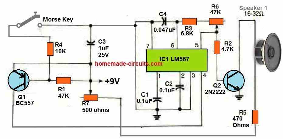
Our second coding practice oscillator circuit makes use of IC1, a 567 phase-locked loop, as the adjustable tone generator. R6 controls the oscillator's frequency, while the C5 value may be modified to alter the oscillator's frequency range.
The value of C5 should be increased to decrease the oscillator's frequency range and decreased to increase it.
Whenever the Morse key is closed, the PNP transistor Q1 feeds voltage to the 567 via its pin#4. This instantly activates the LM567 oscillator frequency at pin#5.
Transistor Q2, a general-purpose NPN transistor amplifies the frequency and operates the speaker. Q2 also simultaneously buffers the IC's oscillator output. The output loudness is controlled via potentiometer R7.
Wireless Code Practice Oscillator

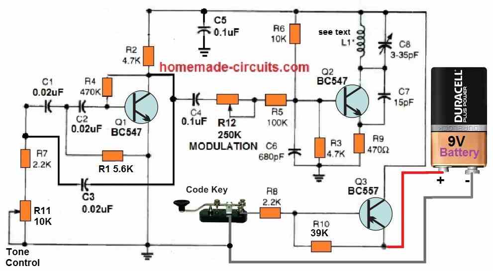
The next circuit, which is seen above, is a tone-modulated, moderate power FM transmitter. This circuit may be used with any FM radio receiver to simulate actual wireless code practice communication.
Using transistor Q1 and associated parts, a phase-shift audio frequency generator circuit is created. The frequency of the output tone could be adjusted using potentiometer R11.
In order to function in the standard FM transmission band, transistor Q2 is set up as a high-frequency RF oscillator circuit. The full FM band may be covered by altering C8 and L1's size.
Using C4, R4, and R12, the audio output tone is hooked up to the base of the Q2 transistor. The modulation level is controlled via potentiometer R12. When the code practice key is pressed, transistor Q3 functions as a switch to power on the FM transmitter.
How to make the Coil L1
Coil L1 is a hand-made air cored coil. Pick a strand of 20-gauge super-enamel copper wire that is 6.5 inches long, then close wound it 50 times around a former which should be around 1/4 inch in diameter.
Keep each end of the former approximately 1/4 inch free. Secure the coil over the former after removing the insulating enamel from the wire ends. The final coil should measure a total of around 1/4 inch.
The circuit might be constructed on a veroboard using the shortest interconnecting wires available.
How to Test
It's simple to test the circuit. Lock the code practice key while adjusting R11 and R12 in the middle positions.
Then carefully tweak C8 after setting your FM receiver to a suitable FM band on the lower end of the dial. As soon as the code practice tone becomes audible, R11 could be adjusted for the appropriate tone frequency.
On the other hand R12 could be tweaked for adjusting the tone volume. If your oscillator is not tuning to the upper spectrum of the band, you can gently try stretching the windings of L1 and fine tune the settings.
The effective range of this wireless code practice oscillator circuit could be enhanced by connecting a very short antenna to the emitter of Q2.
Using IC 4049
The following circuit is another flexible oscillator for coding practice with an adjustable frequency and volume control.

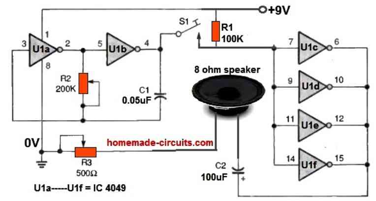
Small bands that are keen on learning and using the code should particularly use the module. The oscillator's core is a solitary 4049 CMOS hex inverting buffer.
And the adjustable audio oscillator circuit is made up of inverters U1a and U1b. The CW (Morse code) key S1 connects the oscillator's output to the speaker-driver circuit. The potentiometer R2 controls the oscillator's audio frequency and sound, while the potentiometer R3 controls the speaker volume.
Wireless Morse Code Receiver Circuit
For ardent Morse operators among radio amateurs, this straightforward wireless receiver circuit offers an off-air morse code monitor that operates on all bands, even up to two meters, without the need for tuning.

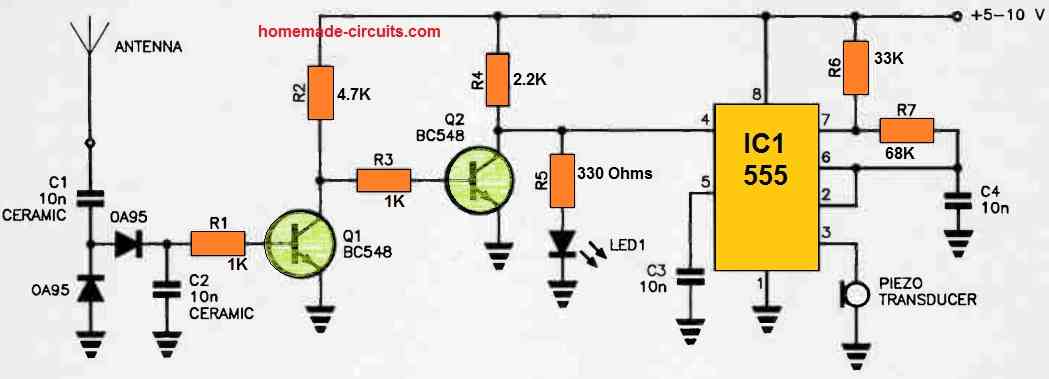
Using a piezo transducer and an LED, it gives both auditory and visible information.
The antenna, which is connected to a voltage doubler rectifier consisting of two 0A95 germanium diodes, detects RF bursts. These energize Q2, which supplies Q1 with base current.
This functions for the period of each dot and dash, and each RF burst causes Q1's base current to swiftly deplete C2 to around half a volt. Q2 remains often turned on since base current travels to it through R2 and R3.
This inhibits the 555 by keeping pin 4 of the 555 [reset] low. Q1 turns on and Q2 shuts off following each RF burst.
Each RF burst will cause the 555 to oscillate in time. The piezo transducer generates the high audio pitch at which it oscillates.
During each RF burst, LED1 will continue to illuminate regardless of whether Q2 is off since current flows through R4 and R5.
The circuit may be powered by any source that is between 5 and 10 volts. You may put a resistor in series with the piezo transducer and the 555's pin 3 to decrease its volume.
The ideal range is between a few hundred and a few thousand Ohms. A short, adjustable telescopic whip can be used as the antenna.
For maximum sensitivity, install this whip and the diodes OA95 close to your antenna. The remaining components should be stored in an appropriate compact box in the shack.
Morse Code Oscillator using a Single UJT
It is simple to create a Morse code practice oscillator using only a UJT, a transistor, and a handful of basic components as shown below.

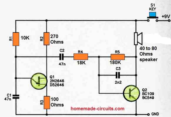
Here's how it operates:
Q1 functions as a typical UJT oscillator, generating a signal with a frequency of a few hundred Hertz.
This resulting sawtooth waveform, which has an amplitude of a few volts, is directed to the base of the output amplifier, Q2, through C2 (to provide DC decoupling) and R4. R5 is responsible for supplying the necessary bias to Q2.
To listen to the Morse code tones, you'll need either a high-impedance speaker or, for a more discreet option, low-impedance (dynamic) headphones that won't disturb those around you.
To control the output, simply incorporate the key contacts in series with the positive rail connected to the 9V battery.
Capacitor C3 plays a role in smoothing out some of the unevenness in the sawtooth sound produced by the UJT oscillator.