In this post I have explained a delay OFF adjustable motor controller circuit so that the motor can be assigned a fixed predetermined operating time, or delay OFF time. The idea was requested by Mr. Cribey
Technical Specifications
I really like your website. It is very helpful for so many people.
I am trying to control a 36RPM geared 9V motor speed and time that it is on in the reverse direction only (counter-clockwise).
In effect I would like to use a 5V USB adaptor plug (like the ones we use for our phones) to power the motor on for a chosen speed and for a chosen amount of time.
BOTH the speed and time need to be adjustable (potentiometers maybe?) to get the exact right time for the motor to be on for, and at the correctly chosen speed.
Any help would be really appreciated.
Regards,
Cribey

The Design
The proposed motor speed controller circuit presented here features an adjustable PWM speed control and an adjustable delay control for the associated motor, which needs to be controlled.
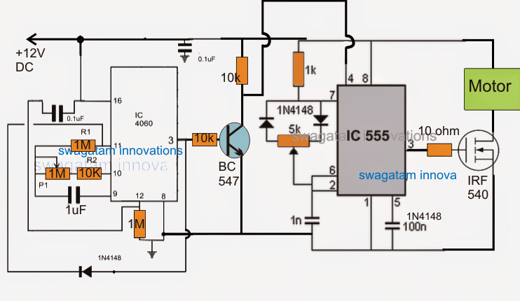
As may be seen in the above diagram, the circuit incorporates two discrete stages, one consisting of the versatile IC 4060 and the other using the work horse IC 555.
Basically both these are timer ICs by nature, however here the IC 555 is configured as a PWM controller whose PWM output is adjustable using the associated 5K pot.
Therefore this stage takes care of the motor speed control and may be set to any desired speed by manually adjusting the 5K pot.
Now as requested, the motor needs to be switched ON only for a particular duration of time, and this is implemented by the 4060 C stage. The delay time which needs to be fixed for enabling the motor to be switched OFF once this elapses is adjusted by the 1M pot associated with pin#10 of the IC 4060 and indicated as P1, the 1uF capacitor also becomes directly responsible for determining the time delay for which the motor may remain switched ON.
When power is switched ON, the IC switches ON the motor and allows it to operate at a particular speed as specified by the adjustment of the 5K pot.
Also simultaneously the IC 4060 begins counting, and as soon as the specified time span elapses, pun#3 of this IC goes high triggering the NPN BC547 transistor into conduction.
The transistor grounds the pin#4 of the IC555 thereby completely disabling the IC 555 and the mosfet at its pin#3, such that the connected motor instantly comes to a halt.
The diode connected across pin#3 and pin#11 of the IC 4060 makes sure that the above condition stays latched until the power is switched OFF and ON again for initiating a fresh cycle.
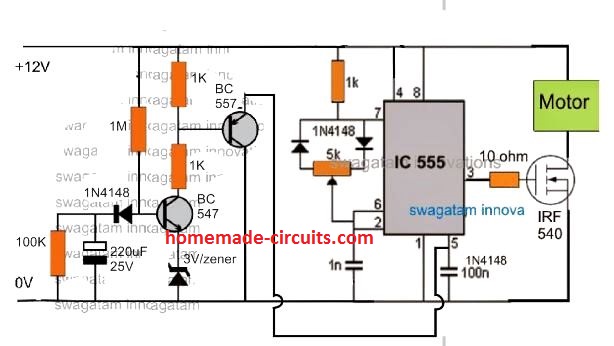
Another simpler version of the above circuit is shown below. It uses a transistorized delay OFF circuit instead of the IC 4060.
