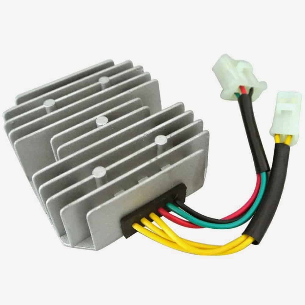
The motorcycle regulator, rectifier tester circuit presented here can be used to test a 6-wire shunt type regulator-rectifiers for a 3-phase charging system of motorcycles. These reg./rectifiers (RR-units) are usually sealed with epoxy and it is considered difficult to find out if the unit is faulty or not.
Designed and Written by: Abu-Hafss
As the name suggests, the unit consists of 2 circuits i.e. the Regulator and the Rectifier. Usually, the wires are coded as below:
Red = BATTERY +
Green = EARTH (Chassis or Battery -)
Black/Yellow = IGNITION
3 Yellow or 3 Pink = 3 PHASES

To test those 2 circuits, the tester circuit is also divided accordingly.
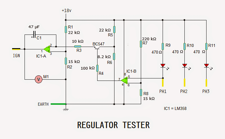
REGULATOR TESTER:
To test the Regulator, its wires are connected to the test circuit as shown. The red wire is not used.

The op-amp IC1-A (along with C1, R1, R2, R3, R5 and R6) is configured as an integrator. R1 & R2 forms a voltage divider, which provides about 7V as reference voltage to the op-amp. R5 & R6 forms another voltage divider to provide ramp-triggering voltage (lower than 7V) thru Q1 BC547 which act as a switch.
Initially Q1 is on, hence a ramp voltage is generated from about 7V to about 16.5V. This ramp is fed into the RR-unit via its IGNITION wire (BLACK/YELLOW).
If the RR-unit is good, its regulator circuit will trip at 14.4-15V (and supply gate voltages to the 3 SCRs inside the RR-unit). The anodes of those SCRs are connected to 3 phases, i.e. the 3 YELLOW wires. The three red LEDs will find path to ground via yellow wires & SCRs hence, they light up.
At the same time, voltage from one of the phases is fed into pin# 5 of IC1-B which is configured as voltage comparator. It compares it with the reference voltage assigned by voltage divider R7 & R8. Since the voltage at pin#5 is lower than the ref. voltage at pin# 6, the output at pin# 7 becomes low.
This switches off Q1 thereby cutting off the ramp-triggering voltage. The ramp voltage comes to a halt. This regulated voltage (14.4 - 15V) can be read with voltmeter M1.
If any of the LEDs does not light up or none of the LEDs light up, it indicates that one or more SCRs are bad. If the voltmeter reads around 16.5V, it indicates the regulator circuit is not working.
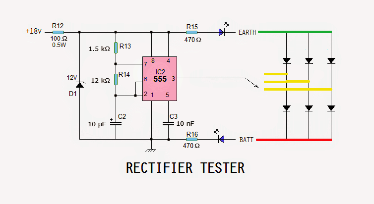
RECTIFIER TESTER:
The rectifier section of RR-unit consists of only 6 rectifier diodes as shown. The wires are connected as shown. The Black/Yellow wire is not used.

IC2 is a 555 which is configured as an astable vibrator. Since the supply voltage is 18V and max voltage for 555 is 15V, a zener diode D2 is introduced to protect the IC.
The output is connected to 1 yellow wire at a time. Both the LEDs should blink, indicating that the corresponding rectifiers are good. If only one LED or no LED blinks, it indicates one or both rectifiers are bad.
Now, the connections of red and green wires are interchanged. If one or both LEDs blink, it indicates that the rectifiers are short (bad).
p.s. I have tested the above explained motorcycle regulator, rectifier tester circuit
-Abu Hafss
