In this article I have explained regarding a motorized sun shade circuit which can be used for achieving an automatic motorized extension and retraction of sun shades or hoods.
The idea was requested by Mr. Sriram KP
Circuit Objectives and Requirements
- I have made wireless water tank controller with manual on-off switch, automatic steps light, soft switch room lights-fan controller, balcony timer lights.
- Now my home is partially like iron man home... 😀 Thanks to u lot. Now I like to make a motorized sun shade to my home balcony.
- Now am manually rolling the screen. I want to make it motorized. Could u pls help me out with a circuit?
- Am having a motor and a driver for it. I have to control the motor driver with the relay with a push to on.
- The motor have to run front and back ( to roll the screen up and down)with two push-to-on switch for 10 seconds.
- Once I press the "up" push-to-on switch means the motor should run for 10seconds (the screen will roll up) and should stop. and "up" switch should not work again( bcoz the screen is already rolled up).
- And now down switch should work now to roll down. And "down" switch should also have the same condition( should not work again, bcoz already rolled down) Thanks.
Circuit Diagram

The Design
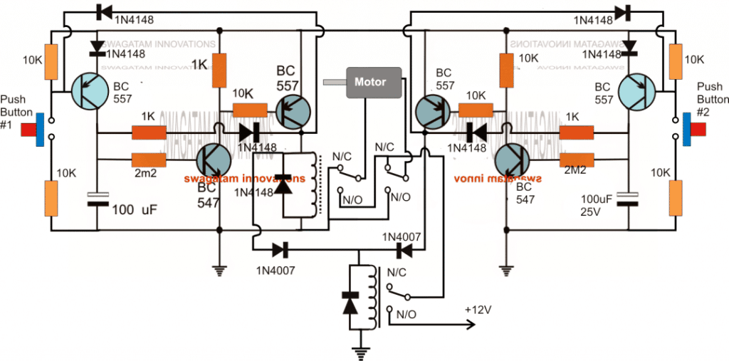
The proposed automatic motorized sunshade timer circuit can be seen in the above diagram.
Basically the design is made up of two transistor timer circuits using pairs of complementary NPN (BC547) and PNP (BC557) transistors. Two identical stages can be seen on either sides of the motor consisting the individual push buttons for the triggering.
The BC557 associated with the relay along with the complementing BC547 transistor forms the timer circuit in conjunction with the 2M2 resistor and the 100uF time determining components.
The other BC557 at the extreme ends of the circuit are included to implement the disabling of the push buttons once these are pressed, meaning once any of the push button is pressed the BC557 associated with it is disabled with the positive feed back signal from the relay driver BC557 collector.
This makes sure that the push buttons can be pressed only once during the triggering, and the subsequent pressing produces no effect until the time is elapsed and the timer is switched OFF
Now let's see how the relays become responsible for executing the motor reverse forward actions in response to the push button activation.
When power is applied to the circuit, the relay situation can be expected to be exactly as indicated in the diagram, that is at the N/C contacts and in the standby position.
The motor stays inactive because the lower relay contacts is not supplying the required positive to the motor via the upper DPDT relay contacts.
Let's assume the left push button #1 is pressed. This instantly activates the DPDT relay associated with the left timer circuit stage.
The lower SPDT also activates through 1N4007 diode link, causing all the relay contacts closing at their respective N/O states.
This action provides the required supply to the motor and allows it to the rotate towards the corresponding direction. The timer begins counting and after the stipulated time is over the relays are switched OFF, halting the motor.
Assuming the above procedures caused the motor to rotate clockwise, implies that pressing push#2 should cause the motor to rotate anticlockwise.
When push button#2 is pressed the right side timer is activated, however this time the DPDT relay does not react and continues to be at the N/C, but the lower SPDT surely activates providing the positive supply to the DPDT relay contacts.
With the DPDT across the N/C contacts allows the motor to get a reversed voltage causing it to rotate in the anticlockwise direction.
Design Flaw
Although the above explained motorized sun shade timer circuit looks great, it has a technical drawback.
The drawback lies in the fact that the push button are disabled only while the relevant timer is counting, and is enabled as soon as the timer has stopped counting or is reset.
This situation makes the push buttons vulnerable to a repeat triggering at the wrong side causing undesired loading of the motor.
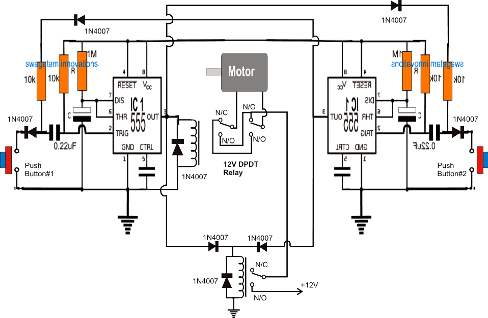
An identical design using the IC 555 solves this issue and ensures a permanent disabling of the push button once the associated timers have stopped counting.

