In this post I have explained a simple water sensor with pump starter circuit for switching a pump motor during municipal water supply periods. The idea was requested by Mr. Hitesh Thapa.
Technical Specifications
Is it possible to make a automatic water pump starter which turns On only when the city supply line has water flowing.
Here is the scenario.
- City Supply Line opens only for 1 hour anytime during 6AM - 10AM or rarely sometimes in the evening depending on the water guy.
- We need to keep a watch during these times and keep the main tap open to see if the water has come.
- Once the water has come, we turn on the water pump attached to the main supply line to pump water into our underground water tank.
Could this be automated, like we install some sensor between the water pump and the main supply line that detects water and turns on the motor only when the supply is in full flow?
I have made the water level indicator at home from watching some videos online and it works fine for the overhead tank at home but this one seems to be tough nut to crack :).
Any help is highly appropriated.
Thanks,
Hitesh Thappa
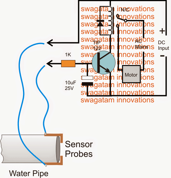
Circuit Diagram

Parts List
- Resistor 1k, 1/4 watt, 5% CFR = 1 no
- Capacitor 10uF/25V Electrolytic = 1 no
- Transistor TIP122 = 1no
- Relay 12V/30 Amp/ SPDT = 1no
- Diode 1N4007 = 1no
- Stainless steel metal for the probes
- 220 V AC to 12 V DC adapter = 1no
The Design
The circuit design of the proposed municipal water sensor with pump starter is very simple as may be witnessed in the shown diagram.
A Darlington TIP 122 transistor becomes the main active sensing device in the circuit. The device being a Darlington is very sensitive and thus becomes specifically suited to the application.
Its base and the positive DC are together clamped as probes across the water pipe mouth where the incoming utility water is intended to be sensed.
In absence of water the probes stay separated with air gap which renders a very high resistance across the probes which in turn keeps the transistor/relay stage switched off.
The 10uF capacitor at the base of the transistor ensures that the transistor does not get rattled or disturbed by external noises trying to make way through the sensor wires.
When utility water supply initiates, the pipe mouth begins throwing water into the adjoining tank, the speed of the water through pipe brushes across the probes creating a relatively low resistance across it.
This low resistance allows the positive DC to reach the base of the BJT triggering it into conduction...the transistor now conducts and switches ON the relay, the relay contacts shift position and switch ON the connected pump.
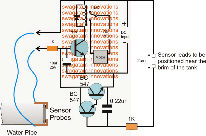
Upgrading the above municipal water sensor into an overhead tank overflow cut off circuit
The discussed circuit in the above section can be appropriately enhanced with an additional feature which will enable the circuit to sense an overhead tank full situation and switch OFF the relay along with the pump motor. The upgraded circuit design can be viewed below:

Parts List
- Resistor 1k, 1/4 watt, 5% CFR = 2 no
- Capacitor 10uF/25V Electrolytic = 1 no
- Capacitor 0.22uF PPC = 1no
- Transistor TIP122 = 1no
- Transistor BC547 = 2nos
- Relay 12V/30 Amp/ SPDT = 1no
- Diode 1N4007 = 1no
- Stainless steel metal for the probes
- 220 V AC to 12 V DC adapter = 1no
