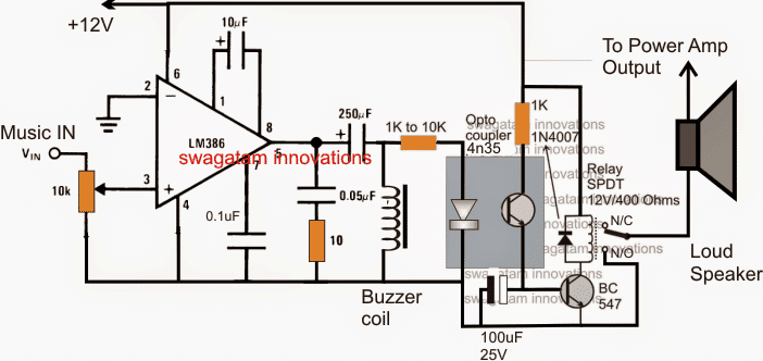
The circuit idea I have explained below enables a power amplifier loudspeakers to switch ON only when there's an input music available, otherwise it makes sure that the loudspeakers remain shut off. The idea ws requested by Mr. David Alda.
Technical Specifications
Your site is just awesome.
I'm hoping you can post a tweak to your post of 10-1-2013 entitled:
Sound Activated Automatic Amplifier Mute Circuit
I need the opposite of that circuit. What I need can be used in recording studios, broadcast studios, etc.
When the input is very low (or none), the output of the amp will be muted. When there is input sound, the amp will function un-muted. The amp needs to have enough power to power a computer type speaker at moderate to high volume levels.
As it will be used in real life:
When computer recording software (or a PC sound card) is not sending out any sound, the circuit will clamp the output so that zero noise is heard in the speaker in the studio. But when the recording software is sending out an input signal, the amp will function normally and drive the studio speaker at an adequate volume level.
On behalf of all those you have helped, thank you. May you be blessed in every way.
Is there any audio I can voice for you for free?
David Alda
Voice over talent & audiobook narrator

The Design
The requested circuit for implementing a music activated amplifier speaker can be witnessed in the figure above.
The idea looks pretty simple but consists of crucial stages which cannot be replaced by any other form of circuit stages.
The music feed (extracted from the power amp input) is applied to the input of an LM386 mini amplifier circuit set at a gain of 200, which is maximum gain for this IC.
The hi gain setting allows the amplifier to sense even the minutest level of input signals, although this may be set as per the users preference through the given input volume control pot.
Using LM386 as Music Amplifier
In the presence of a music input, the LM386 amplifies it to the required levels and the output is acquired at the output pin#8 of the IC through an AC coupling 250uF capacitor, and applied across an condenser inductor which should be preferably a "buzzer coil". You can see the image of a buzzer coil below:

Function of Buzzer Coil
The buzzer coil makes sure that the amplified music is further boosted to higher levels in order to make it compatible with an opto coupler input LED.
The optocoupler 4n35 can be seen connected across the coil, the built in LED inside the opto responds to this music voltage and lights up which in turn switches ON the internal photo transistor of the opto.
The emitter of the photo transistor inside the opto now begins conducting so that the connected external relay driver transistor BC547 receives enough base drive to activate the relay.
The relay switches ON immediately in response to the above procedures and connects the power amplifier's output with the loudspeakers.
Conversely, in an absence of a music signal or insufficient music at the input, the LM386 and the output coil are unable to sustain any voltage at the output, which keep the opto and the relay driver stages switched OFF, the loudspeakers also stay off because of this, until a legit music input is sensed.
The 100uF capacitor at the base of the BC547 transistor makes sure that the relay does not chatter in case the input carries a fluctuating or intermittent music signal.
