In the field of audio amplifiers OCL stands for Output Capacitor-Less Amplifier design.
How it Works
In this OCL type of amplifier topology or configuration, the power output stage is directly coupled to its preceding driver stage without coupling capacitors.
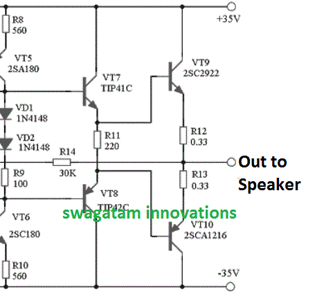
The following figure shows a typical OCL amplifier output stage, as can be seen, the VT9/VT10 power BJTs bases are directly linked with the VT7, VT8 BJT stage, and the same can be seen with the earlier stage, wherein no capacitors are involved for the indicated couplings.
Circuit Example


Although there could be many versions of OCL amplifiers, mostly the push-pull type output configurations is popularly employed in OCL designs. as shown above.
Advantages
The OCL configuration could become popular due to some distinct advantages it possesses, compared to the other forms of amplifier topologies. The main features can be learned from the following points:
- Elimination of capacitor coupling enables the unit to become very sleek and compact, and also helps to make the design very cost effective.
- The OCL design ensures enhanced immunity to the so called "motorboat oscillations" in amplifiers.
- The design also allows the unit to deliver high power outputs even at lower input audio frequencies or DC supplies.
Disadvantages
Although OCL amplifiers come with a few great advantages, it may exhibit a couple of marked disadvantages, as given below:
- The power devices show a tendency of dissipating significant amounts of power.
- In amplifiers where the bias points are poorly controlled, an OCL amplifier could pass the DC content into the loudspeakers, causing heating of the loudspeaker.
sir are you also the maker. of. socl. boom. tef which. is powered up. to 90vdc can you teach me how to make. it 140vdc without dc output stable with 12 output power. transistor of 2sc5200 and 2sa1943 thanks you
Sorry wilfredo, I have no idea about this concept!
Your article replacing the BJT with Mosfet could be misleading regarding enhancement mode Mosfets.
The BJT base – emitter resistor cannot be removed using a enhancement-mode mosfet for bias but certainly with a depletion mode device because its self biased nature for small signal applications.
Perhaps you can share your knowledge with a small signal common gate single stage preamp design of low distortion with a gain of about 3-5 inputting a direct coupled 30- 45 ohm input source for my laptop.
I will take care of the output loading to the following stage.
The enhancement mosfet would be a BS 170 at about 2-3 ma of drain current.
A attached file design would be greatly appreciated.
Love your designs and articles.
Claude…
Thank you, however I could not find where I wrote that the base/emitter resistor should be removed while replacing BJT with MOSFET?
I am not good with designing preamps or amps so can’t precisely suggest the circuit you are looking for, however I have an extensive article regarding preampms under the following link, hope this helps:
https://www.homemade-circuits.com/small-amplifier-circuit/
Could you please send the PCB layout of your circuit 100w power amp using 2N3055 transistors?
I have the entire design in an old elektor electronics magazine, if possible will try to publish it soon….