The 741 is a popular general-purpose operational amplifier (op-amp) IC that was introduced by Fairchild Semiconductor in 1968. It has since become one of the most widely used op-amp ICs in the world, due to its versatility and low cost. Below is a typical datasheet for the IC 741:
General Specifications:
- Supply voltage: +/- 10 to +/- 18V
- Input voltage range: +/- 15V
- Output voltage range: +/- 14V
- Input current: 500 nA
- Output current: 25 mA
- Unity gain frequency: 1 MHz
- Slew rate: 0.5 V/us
- Input resistance: 2 MOhm
- Output resistance: 75 Ohm
- Voltage gain: 200,000
Pinout Configuration:
The pinout details for the IC 741 are as given below:

- Offset null
- Inverting input (-)
- Non-inverting input (+)
- V- (negative power supply)
- Offset null
- Output
- V+ (positive power supply)
- NC (no connection)
Features:
- High gain (typically 200,000)
- Wide input voltage range
- Low input bias and offset currents
- High output current
- Compatible with industry-standard TTL and MOS logic
- Short-circuit protection
Applications:
- Amplification of analog signals
- Filtering and signal conditioning
- Oscillators and waveform generators
- Voltage regulators
- Comparator circuits
- Audio and video signal processing
For more IC 741 application circuits you can refer to the following article:
Note: This datasheet is for general reference only, as specific features and specifications may vary depending on the manufacturer and version of the IC. It is important to consult the datasheet for the specific IC being used in any given application.
Offset Nulling
The operational amplifier (op-amp) of IC 741 uses a method called offset nulling to reduce or eliminate the input offset voltage.
When the input voltages are the same (that is, when there is no differential input voltage), a very tiny voltage may exist between the op-amp's inverting and non-inverting inputs.
In situations where great precision and accuracy are required, this offset voltage might lead to errors in the op-amp's output.
In other words, the offset voltage can cause the output voltage of the 741 to be somewhere between 0.5 V or 2 V when it is actually supposed to be zero. Meaning, in situations where the op amp output is supposed to show 0 V at the output pin#6, it might instead show a voltage higher than 0.5 V, which can be very undesirable.
How to Eliminate 741 Offset Voltage Problem
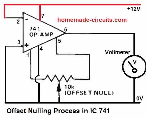
The 741 op-amp has two pins with the label "OFFSET NUL" to reduce or remove this offset voltage.
You simply have to connect the two outer pins of a 10 K preset across the OFFSET NUL pinouts of the 741, which are pin#1 and pin#5, and connect the center pin of the preset to the ground line of the op amp.
Next, connect a voltmeter across the pin#6 and ground of the op amp and slowly adjust the 10 K preset until you get a perfect zero volts at the output of the 741 IC.
Remember the above procedures will need to be done while the IC is powered ON with DC. Without supply voltages the above process will not work.
The complete circuit diagram for implementing the offset nulling in IC 741 is shown in the following circuit diagram:

IC 741 Voltage Regulator (Application Circuit)

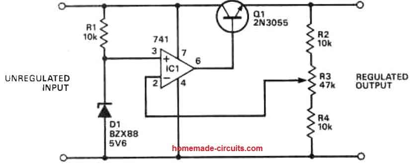
This is a voltage regulator circuit using IC 741 and 2N3055 transistor. Non-inverting pin of 741 is clamped to a 5V zener at the unregulated DC side of the power supply.
The inverting input pin is configured as the feedback and is connected to the slider arm of a pot, the outer pins of the pins are connected to the output regulated DC supply rails.
The output of the op amp 741 is connected to the base of a 2N3055 transistor.
The collector of the transistor is connected to the unregulated + DC input supply, while the emitter forms the output which supplies the regulated DC output.
The output regulated DC voltage can be changed by adjusting the pot value.