In this post I will show how to construct a battery eliminator / DC variable power supply which will automatically cut-off the supply, if the current flow through the load exceeds the preset threshold level.
By Girish Radhakrishanan
Main Technical Features
The proposed over current cut-off power supply circuit using Arduino has 16 X 2 LCD display, which is used to show case the voltage, current, power consumption and preset threshold current limit in real time.
Being an electronics enthusiast, we test our prototypes on a variable voltage power supply. Most of us own a cheap variable power supply which might don’t sport neither voltage measuring / current measuring feature nor short circuit or over current protection built in.
That’s because power supply with these mentioned features can bomb on your wallet and will be overkilled for hobby usage.
Short circuit and over current flow is a problem for beginners to professionals and beginners are prone to this more often because of their inexperience, they might reverse the power supply’s polarity or connect the components in wrong way, etc.
These things can cause the current flow through the circuit unusually high, resulting in thermal runaway in semiconductor and passive components which results in destruction of valuable electronic components. In these cases ohm’s law turns into an enemy.
If you never made a short circuit or fried circuit, then congrats! You are one of few people who are perfect in electronics or you never try something new in electronics.
The proposed power supply project can protect the electronic components from such frying destruction, which will be cheap enough for an average electronics hobbyist and easy enough to construct one for who is slightly above beginner level.
The Design
The power supply has 3 potentiometers: one for adjusting the LCD display contrast, one for adjusting the output voltage ranging from 1.2 V to 15V and the last potentiometer is used for setting the current limit ranging from 0 to 2000 mA or 2 Ampere.
The LCD display will update you with four parameters every second: the voltage, current consumption, pre-set current limit and power consuming by the load.
The current consumption via load will be displayed in milliamps; the pre-set current limit will be displayed in milliamps and the power consumption will be displayed in milli-watts.
The circuit is divided into 3 parts: the power electronics, the LCD display connection and power measuring circuit.
These 3 stage may help the readers to understand the circuit better. Now let’s see the power electronics section which controls the output voltage.
Schematic diagram:
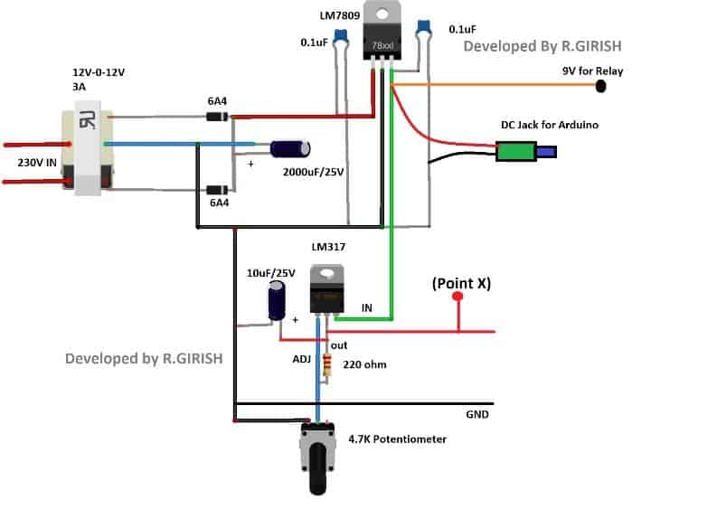
The 12v-0-12v / 3A transformer will be utilized for stepping down the voltage, the 6A4 diodes will convert the AC into DC voltage and the 2000uF capacitor will smooth out the choppy DC supply from diodes.
The LM 7809 fixed 9V regulator will convert the unregulated DC to regulated 9V DC supply.
The 9V supply will power the Arduino and relay. Try to use a DC jack for arduino’s input supply.
Don’t skip those 0.1uF ceramic capacitors which provide good stability for output voltage.
The LM 317 provides variable output voltage for the load which is to be connected.
You can adjust the output voltage by rotating the 4.7K ohm potentiometer.
That concludes the power section.
Now let’s see the display connection:
Connection Details
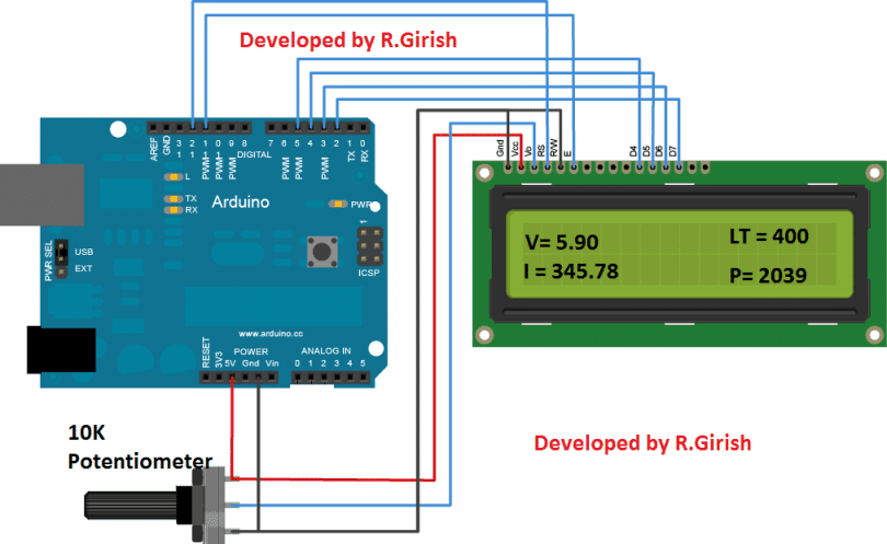
There is nothing to explain here much, just wire up the Arduino and LCD display as per the circuit diagram. Adjust the 10K potentiometer for better viewing contrast.
The above display shows the sample readings for the four parameters mentioned.
Power Measuring Stage
Now, let’s see the power measurement circuit in detail.
The power measuring circuit comprises of voltmeter and ammeter.
The Arduino can measure voltage and current simultaneously by connecting the network of resistors as per the circuit diagram.
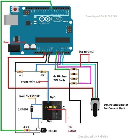
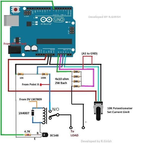
Relay Connection Details for the above Design:
The four 10 ohm resistors in parallel which forms 2.5 ohm shunt resistor which will be utilized for measuring the current flow through the load.
The resistors should be at least 2 watt each.
The 10k ohm and 100k ohm resistors helps the Arduino to measure voltage at the load. These resistor can be one with normal wattage rating.
If you want to know more about the working of Arduino based ammeter and voltmeter check out these two links:
Voltmeter: https://www.homemade-circuits.com/2016/09/how-to-make-dc-voltmeter-using-arduino.html
Ammeter: https://www.homemade-circuits.com/2017/08/arduino-dc-digital-ammeter.html
The 10K ohm potentiometer is provided for adjusting the maximum current level at the output.
If the current flow through the load exceeds the pre-set current the output supply will be disconnected.
You can see the preset level in the display it will be mentioned as “LT” (Limit).
Say for example: if you set the limit as 200, it will gives out current till 199mA. If the current consumption gets equal to 200 mA or above the output will be immediately cut-off.
The output is turned on and off by the Arduino pin #7.
When this pin is high the transistor energizes the relay which connects the common and normally open pins, which conducts the positive supply for the load.
The diode IN4007 absorbs the high voltage back EMF from the relay coil while switching the relay ON and OFF.
Program Code:
//------------------Program Developed by R.GIRISH------------------//

#include <LiquidCrystal.h>

#define input_1 A0

#define input_2 A1

#define input_3 A2

#define pot A3

LiquidCrystal lcd(12, 11, 5, 4, 3, 2);

int Pout = 7;

int AnalogValue = 0;

int potValue = 0;

int PeakVoltage = 0;

int value = 0;

int power = 0;

float AverageVoltage = 0;

float input_A0 = 0;

float input_A1 = 0;

float output = 0;

float Resolution = 0.00488;

float vout = 0.0;

float vin = 0.0;

float R1 = 100000;

float R2 = 10000;

unsigned long sample = 0;

int threshold = 0;

void setup()

{

lcd.begin(16,2);

Serial.begin(9600);

pinMode(input_3, INPUT);

pinMode(Pout, OUTPUT);

pinMode(pot, INPUT);

digitalWrite(Pout, HIGH);

}

void loop()

{

PeakVoltage = 0;

value = analogRead(input_3);

vout = (value * 5.0) / 1024;

vin = vout / (R2/(R1+R2));

if (vin < 0.10)

{

vin = 0.0;

}

for(sample = 0; sample < 5000; sample ++)

{

AnalogValue = analogRead(input_1);

if(PeakVoltage < AnalogValue)

{

PeakVoltage = AnalogValue;

}

else

{

delayMicroseconds(10);

}

}

input_A0 = PeakVoltage * Resolution;

PeakVoltage = 0;

for(sample = 0; sample < 5000; sample ++)

{

AnalogValue = analogRead(input_2);

if(PeakVoltage < AnalogValue)

{

PeakVoltage = AnalogValue;

}

else

{

delayMicroseconds(10);

}

}

potValue = analogRead(pot);

threshold = map(potValue, 0, 1023, 0, 2000);

input_A1 = PeakVoltage * Resolution;

output = (input_A0 - input_A1) * 100;

output = output * 4;

power = output * vin;

while(output >= threshold || analogRead(input_1) >= 1010)

{

digitalWrite(Pout, LOW);

while(true)

{

lcd.clear();

lcd.setCursor(0,0);

lcd.print("Power Supply is");

lcd.setCursor(0,1);

lcd.print("Disconnected.");

delay(1500);

lcd.clear();

lcd.setCursor(0,0);

lcd.print("Press Reset the");

lcd.setCursor(0,1);

lcd.print("Button.");

delay(1500);

}

}

while(output >= threshold || analogRead(input_2) >= 1010)

{

digitalWrite(Pout, LOW);

while(true)

{

lcd.clear();

lcd.setCursor(0,0);

lcd.print("Power Supply is");

lcd.setCursor(0,1);

lcd.print("Disconnected.");

delay(1500);

lcd.clear();

lcd.setCursor(0,0);

lcd.print("Press Reset the");

lcd.setCursor(0,1);

lcd.print("Button.");

delay(1500);

}

}

lcd.clear();

lcd.setCursor(0,0);

lcd.print("V=");

lcd.print(vin);

lcd.setCursor(9,0);

lcd.print("LT=");

lcd.print(threshold);

lcd.setCursor(0,1);

lcd.print("I=");

lcd.print(output);

lcd.setCursor(9,1);

lcd.print("P=");

lcd.print(power);

Serial.print("Volatge Level at A0 = ");

Serial.println(analogRead(input_1));

Serial.print("Volatge Level at A1 = ");

Serial.println(analogRead(input_2));

Serial.print("Voltage Level at A2 = ");

Serial.println(analogRead(input_3));

Serial.println("------------------------------");

}
//------------------Program Developed by R.GIRISH------------------//
By now, you would have gained enough knowledge to construct a power supply which protect you valuable electronic components and modules.
If you have any specific question regarding this over current cut-off power supply circuit using Arduino feel free to ask in comment section, you may receive a quick reply.