In this post I have explained about a simple mechanism, and a circuit which will enable a patient's IV drip bottle system to sound an alarm whenever it gets almost empty, and needs a replacement.
The warning circuit will help doctors and the concerned employees to concentrate on other important matters while the drip systems are active, since after installing this unit they won't have to frequently check and be bothered about the level of the liquid inside drip bottles attached with the patients.
Set up Configuration
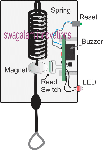
The proposed IV drip bottle empty alert warning indicator is configured using a mechanical spring stage attached with an electronic stage as shown below:

In the figure above we can see the following things:
An appropriately selected spring mechanism attached on the upper surface of a plastic enclosure.
The lower end of the spring is appropriately terminated outside the enclosure with a hook for hanging the drip bottle.
Within the enclosure, the spring end can be seen attached with a permanent magnet, such that under no load the magnet stays in the indicated position, and in the presence of a load which can be a drip bottle filled with the drip liquid, the magnet is displaced to a lower position and away from its original position.
We can also visualize a reed switch positioned near the magnet at its initial no load position.
The reed switch terminals can be seen wired with a circuit assembled over a PCB, and the PCB bolted inside the enclosure as shown in the design.
There are two additional items in the form of a reset push button, a buzzer, and an LED which become the external protruding parts of the PCB.
In the following section I have explained how the above set up works in conjunction with the warning buzzer circuit, inside the enclosure.
How it Works

The working principle of the drip warning indicator is actually very simple:
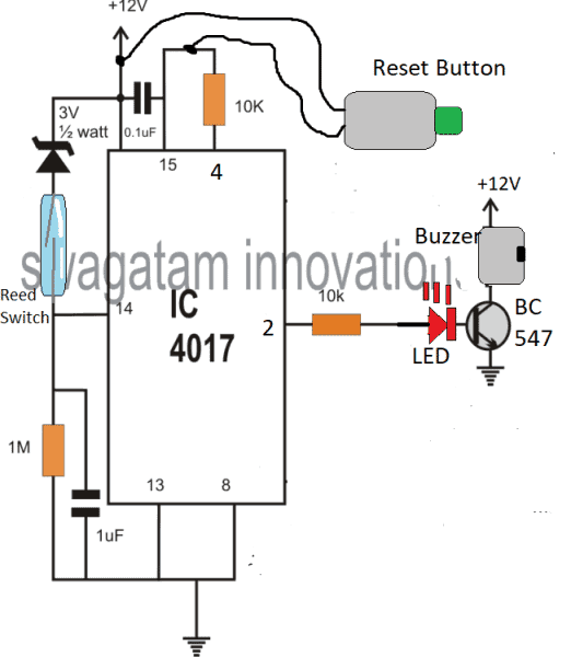
Referring to the image above, initially without a filled drip bottle hung, and the circuit powered ON, the circuit stays inactive, but gets into a standby position.
In this position, the magnet stays near the reed switch in the closed position which causes a positive supply at pin#14 of the IC 4017. However this does not force the IC 4017 to shift its output logic sequence, because simultaneously the supply also resets the pin#15 of the IC through the attached 0.1uF capacitor.
Now, when the drip bottle is attached to the hook, the spring is pulled downward, causing a displacement of the magnet away from the reed switch.
The reed switch instantly opens, removing the positive supply from pin#14 of the IC 4017.
The output of IC 4017 still retains its initial condition, that is the logic stays at the unused pin#3 pinout, due to the negative supply from the 1M resistor.
Let's assume the drip fluid gets used up by the patient, and gradually nears the empty condition.
As soon as this reaches the empty level, the magnet now once again positions itself in its original point where it meets the reed switch.
The reed contacts now closes yet again, causing a positive pulse on pin#14 of IC 4017.
This time the IC reacts to this signal and shifts the high logic from its unused pin#3 to pin#2.
The transistor at pin#2 now activates, and switches ON the buzzer alarm, alerting the concerned member in the vicinity regarding the empty drip bottle. The LED being in series with the transistor base also lights up providing additional warning indication.
The buzzer continues to buzz and is held in the activated position until the concerned member comes and presses the reset button to revert the circuit in its earlier standby position.
In this position the unit allows the replacement of the empty drip bottle with a fresh filled drip bottle, so that the cycle is able to continue yet again as explained in the above paragraphs.
Simple Mechanical Approach
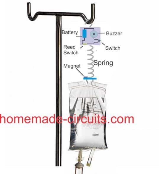
The idea is very simple. The upper enclosure consists of a buzzer, battery assembly with a series reed relay and an ON/OFF switch. The reed relay is positioned at one of the bottom corners of the enclosure.
A spring mechanism is attached at the lower end of the enclosure with a magnet, such that when no drip is hung, the magnet aligns itself at a close proximity to the internal reed relay.
Initially the ON/OFF switch is held in the switched OFF condition, and is switched ON once the drip is hung and the spring is pulled downward moving the magnet away from the reed switch.
Now, as the drip liquid empties its weight decreases and it begins moving upwards due to spring tension, until finally the liquid almost gets over moving the magnet close to the reed. The reed switch now closes switching ON the buzzer.
