

In this part of the article I have explained about an innovative method of converting pedal press mechanism in electric vehicles into a correspondingly varying electrical signal, which may be further used for processing the speed control of the vehicle.
The explained concept will work like an electronic accelerator, which will increase the vehicle speed linearly when the pedal is gradually pressed, and vice versa, using PWM technology
The idea was requested by Mr.Lokesh Maini
Technical Specifications
I am a mechanical guy,currently working on an electric vehicle and i want to control the speed of my motor using pedal . i am not getting a controller for my motor please help me to build my own i'll be highly
thankful
Motor Specifications are 36volt,43amps and 1.5hp brushed dc motor.
The Mechanical Design
An electronic version of a pedal accelerator will primarily require a mechanism to first convert mechanical pressing of the pedal into a correspondingly varying electrical signal, so that this signal can be processed through a signal processor stage for the desired conversion into a practical speed control of the vehicle.
Many concepts can be tried such as by using a piezo load sensor, a capacitive load sensor, by a resonance sensor etc. In this article we'll learn a much simpler method devised by me which incorporates a LED/LDR assembly for achieving the same.
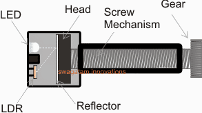
In the electromechanical arrangement shown in the figure above we are able to see the following integrated components:
A small gear attached with a screw mechanism.
The head of the screw having a white mat reflector surface
A LED/LDR assembly positioned in front of the screw head.
How the Proposed mechanism works.
The gear shown in the above figure is to be locked with another gear having a ratio that may be 10 times higher than this gear.
The bigger gear needs to be configured with the pedal mechanism such that it initiates a rotational movement in response to the pressing of the pedal.
The rotational response from the gears will in turn produce a forward motion of the screw head across the chamber where the LED/LDR assembly is located.
The process will cause a proportionately varying amount of reflected light from the LED to be received by the LDR.
This varying data (in the form of a varying resistance) corresponding to the pedal depression can be then fed to a signal processor circuit for enforcing the intended speed control of the particular vehicle.
In the next post we'll learn the signal processor stage using PWM technique.
In the above section I have explained about a simple electromechanical converter assembly for transforming the pedal action into a proportionately varying electrical signal.
Converting Pedal Action to PWM
Now let's study a circuit implementation which will enable us to convert the pedal electric signal into a correspondingly varying PWM signal for the intended motor speed control of the vehicle.
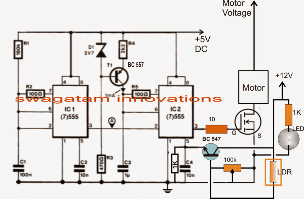
Referring to the above circuit diagram we can assess the circuit operation with the help of the following points:
IC1 is configured as a 80Hz pulse generator having maximum ON time and minimum OFF time as its duty cycle
IC2 is rigged as a comparator which first converts the above 80Hz pulse applied at its pin2 with triangle waves generated at its pin6 and compare the triangle waves with the modulating voltage available at its pin5.
The pin5 modulating voltage is derived from a BJT BC547 emitter which is configured as a common collector with its base connected with the LDR inputs achieved from the pedal actions.
The varying resistances in response to the pedal pressing is compared with the 100K preset setting and a proportionate magnitude of voltage is developed at the base of the transistor which converts the low current input into an equivalent high current signal over pin5 of IC2.
This instantaneous potential level is accepted and processed by IC2 generating proportionate magnitude of PWM signals for the mosfet and the connected motor.
The motor speed is thus controlled and varied as per the fluctuating PWMs in response to the pedal pressings of the vehicle.
The above procedures effectively convert the pedal actions into a controlled operations of the vehicle motor and its speed.
How to Set up the Circuit.
It's very easy.
- Press the pedal to its maximum point such that the screw head reaches to the nearest possible position in front of the LED/LDR assembly.
- Next adjust the 100k preset until pin3 of the IC2 starts generating PWMs with maximum width, this may be confirmed by measuring the voltage at pin3 to be as close as possible to the supply voltage of the circuit, that is 5V.
- Once this is done, the setting up procedure could be assumed to be complete.
- The results could be now verified by pressing the pedal at different levels and checking the motor speed vary in an identical manner.