In this post I have explained a simple mains to generator automatic transfer switch (ATS) which features an initial petrol start which switches to an LPG gas supply via fuel valve changeover switches. The idea was requested by Mr. Junaid.
Technical Specifications
sir i want to make my generator automatic start on petrol then shift the generator on gas and finally turn on the load and when main supply comes it will auto shift the load to main and turn off the generator..
in short i want to use this circuit with automatic ATS for my generator which is placed on 2nd floor. i will very thankful to you if you upload the circuit diagram as soon as possible
my generator is already button/self start.i think that relay will do the job (automatic start) but my main purpose is that the generator should start on petrol then after 10 to 15 second automatic shift it to the GAS/LPG..hope you will help me for this.

Parts List
- R1, R2, R3, R4, R5 = 10K
- C1 = 470uF/25V
- T1, T2 = BC557
- T3, T4 = BC547
- ALL DIODES = 1N4007
- RL1---RL3 = 12V/400 ohms
- RL4 = 12V DPDT, 30amp
The Design
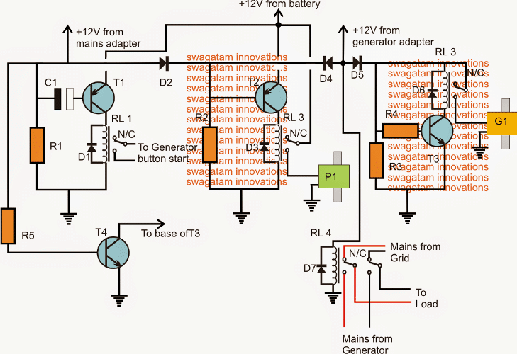
As per the request, the above shown circuit may be incorporated for implementing the proposed generator automatic transfer or changeover relay circuit from petrol to gas using 12V solenoid valves.
The circuit employs a couple of 2-way normally closed solenoid fuel valves for changing over from petrol to gas fuel.
The circuit may be understood with the help of the following explanation:
As soon as mains grid electricity fails, T1 base gets enabled through R1 and C1 and it triggers the RL1 to initiate the connected generator.
RL1 holds on for a few seconds depending the values of R1 and C1 and then deactivates, once this happen the generator can be assumed to have started.
While the above is carried out, simultaneously T2 also switches ON activating RL2 and opening P1 which is a 2-way fuel solenoid valve connected with the petrol tank. Petrol is now allowed to pass to the generator ignition chamber. T2/P1 operates using a chargeable battery supply.
The generator thus is initiated using the petrol from this valve P1 at the onset.
Once the generator starts a 12V adapter connected with the generator output switches ON and sends a 12V supply to the bases of T2 and T3 via D4/D5. This action forces T2 to deactivate shutting of R2 and closing P1 petrol supply...while at the same time T3 switches ON opening G1 gas supply valve by the activation of RL3.
The above execution switches the generator operation from petrol to gas (LPG or CNG)
RL4 makes sure that the load or the appliances are appropriately and automatically transferred from the grid mains to generator mains and vice versa whenever grid mains fails or restores.
In an event when the grid mains returns, T4 disables T3, RL3 and the gas supply to the generator, forcing it to shut off. The entire system now returns to the original mode and the load begins operating via the grid mains AC.
Improved Version
An improved or an upgraded version of the above ATS can be witnessed in the following sections:

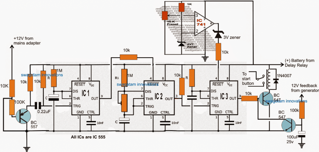
The above diagram shows the "smart" generator starter circuit, which cranks the generator a few number of times and then shuts off. The shutting off is dependent on three conditions:
1) The generator actuates,
2) The stipulated number of cranking is completed without results, 3) The battery is detected to be low.
IC1 and IC3 are configured as monstables, where IC1 is selected to generate a 1 minute high at its pin#3 when AC mains fails, while IC3 is assigned for generating the cranking sequences for 4 or 5 times with 5 seconds period for each cranking.
The center IC2 is rigged as an astable which supplies the cranking triggers to the IC3.
The IC2 preset must be set such that pin3 of IC 2 generates a duty cycle of 20 seconds ON and 2 seconds OFF.
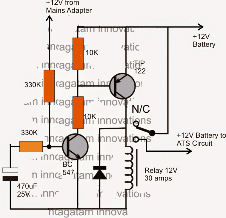
In order to ensure a delayed start ON or a delayed switch OFF the following delay relay circuit may be employed with the above design.
