
Music is a part of our lives, accompanying and enhancing our everyday experiences. While it is easy in electronics to generate a single note, for example, using a simple astable oscillator, one can only dream of the myriad of sounds available on even the most ordinary synthesizers, versatile and almost indispensable instruments today.
A musical note is defined by its frequency, amplitude, and timbre. Long ago, Pythagoras established, by measuring the lengths of vibrating strings, that there exists a simple ratio between the frequencies of different musical sounds.
For instance, the note A (LA in German-speaking countries), particularly in the third octave, vibrates precisely at the frequency of 440 Hz, to such an extent that it serves as a reference by tuning forks or... for the tone heard when you pick up your telephone receiver.
The range of audible frequencies for humans is variable and depends on physiological factors; a piano can resonate with its 88 keys ranging from about 27 Hz to 4000 Hz.
The amplitude of a note corresponds, in a way, to its volume, i.e., the sound intensity perceived by the listener. Occasionally, Italian terms like "forte," "pianissimo," etc., are used to further specify the dynamics in musical scores.
Similarly, even if different instruments were to play the exact same note, it is easy to understand that the timbre of the emitted sound is quite different between a flute and a piano, a violin and a hunting horn.
We do not claim to offer you a means to rival the magnificent electronic instruments available in the market.
However, it seems possible for interested amateurs to build a small note generator that perfectly imitates the characteristic "plucked" sound of a string, such as a guitar, or even the struck string of a piano.
The uniqueness of these notes lies in their combination of a sharp attack and a gradual decay: we refer to this as a damped oscillation, similar to a string that is plucked and vibrates until it comes to a complete stop.
Not wishing to implement a modulation device like those found in electronic instruments (VCA), we will content ourselves with producing an adjustable sine wave that gradually fades away.
Such a signal can also be used to simulate the various percussion instruments (DRUMS) found, for example, in the standardized MIDI nomenclature of synthesizers: drums, snares, barrels, etc., provided, of course, that sufficient amplification and a basic generator for each instrument to be imitated are available.
The basic circuit diagram can be easily adapted with a few careful adjustments. Each generator can be triggered by a push button or, better yet, a normally closed contact activated by a stick!
Circuit Description
The proposed circuit diagram is shown in the following figure.
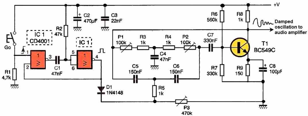
The heart of the circuit is a classic double-T oscillator, named so because of the characteristic arrangement of certain components.
The first upper branch of the T is formed by elements P1 + R3, R4 + P2, and C4. The second branch consists of C5, C6, and R5 + P3.
Oscillation occurs when P1 + R3 equals P2 + R4, and for a specific position of the adjustable P3.
The resulting waveform will be a sinusoidal wave with a significant amplitude and a base frequency determined by the capacitors in the branches of the double-T.
The relationship expressing this frequency can be approximated as follows: f in hertz = 1 / 2π√(P1 + R3) * (R5 + P3) * Cb * C4.
The output of the oscillator is directed through capacitor C7 to transistor T1, which maintains continuous oscillation through the inversion introduced and the feedback connection between the collector of T1 and the other end of the double-T.
The trick is to adjust the oscillator stage so that it does not oscillate spontaneously but rather through a single positive pulse obtained in our diagram from a simple monostable flip-flop.
The proposed classic circuit employs two NOR gates and delivers a very brief positive signal on the rising edge of the input, which is also unique and free from unwanted bouncing.
Diode D1 applies this pulse to one branch of the double-T oscillator, triggering a damped oscillation that needs to be adjusted before use.
The duration and frequency of the signal are variable, and that is precisely the main advantage of the circuit - it can generate a wide range of different sounds: low, high, long, or short, similar to a stringed instrument.
The adjustment of this stage is crucial and requires a lot of patience. The useful variable signal is quite modest and can only be heard after amplification.
The figure below presents a simple amplifier stage that utilizes a small integrated circuit in an 8-pin DIL package capable of delivering a maximum power of 2W under a 12V voltage.
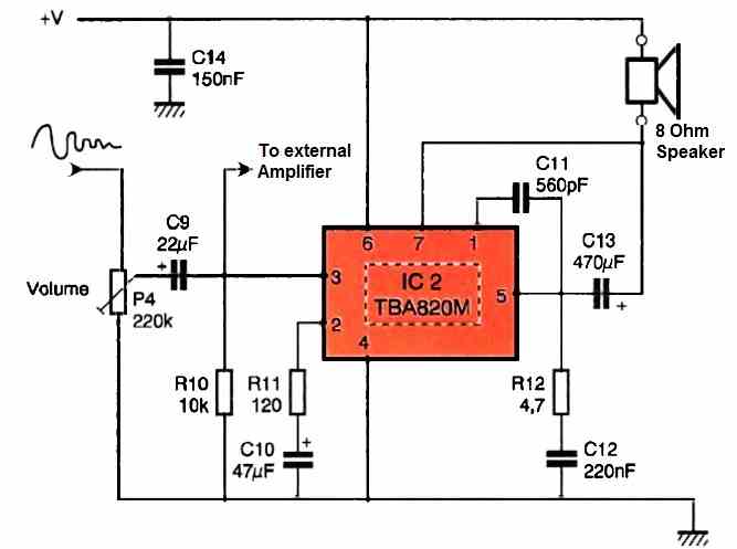
We summarize the essential characteristics of this economical audio amplifier in a small technical box.
The adjustable P4 serves as a volume potentiometer, while capacitor C11 determines the bandwidth, limited here to frequencies below 7 kHz. The constant gain of our class B amplifier depends on the associated components R11 and C10.
The amplified signal is routed through capacitor C13 to the speaker for output. While this rudimentary solution allows you to appreciate the sound produced, it cannot compete with the power of a Hi-Fi system for spectacular results.
Construction
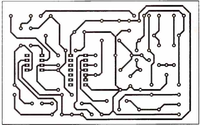
The printed circuit board (PCB) for this piano guitar sound effect generator circuit is of modest dimensions and will be reproduced using the method of your choice as indicated in the figure below, at a scale of 1 as usual.
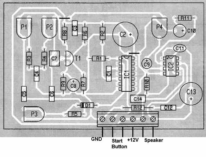
After etching, the components will be mounted according to the layout shown in the figure below, with two horizontal straps that should not be forgotten. Additionally, we recommend using a socket for the integrated circuits.
How to Setup
Assuming you don't have an oscilloscope capable of visualizing the well-adjusted oscillator's sinusoidal wave, no problem.
Connect a 12V power source and the speaker to the designated terminals, then set P4 to mid-position.
Next, slowly rotate P2, for example, after positioning P1 and P3 to any position. Ideally, P1 and P2 should be set to the same resistance value.
When the settings are satisfactory, you will clearly hear a pure continuous signal from the speaker, as it consists of a beautiful sinusoidal wave, similar to the sound of a flute.
Next, you need to "misadjust" the circuit by setting one of the adjustable components to a point that eliminates the oscillation.
Now, a pulse from the monostable should activate the oscillator, producing a damped wave with a pleasing effect that can be adjusted by fine-tuning the various adjustable components.
You can obtain a signal that is more or less brief or more or less "soft." By changing the values of the components in the double-T circuit, you can achieve a different tone, always after adjustment.
Now it's time for you to play and decide whether this prototype deserves to be enclosed as it is, or if it should be combined with other identical modules to create a complete musical system.