

In this post I have explained a method which can be probably used for enhancing a passive infrared sensor ability to detect even a static or stationery human presence. This feature is normally not possible with the conventional PIR sensors.
How PIR Detect Human Presence
I have already discussed many PIR based motion detector applications in this website, however all these applications requires the human presence to be constantly in motion in order to keep the PIR detecting their presence, this appears to be a big drawback which prevents these units from sensing a constant or a stationary human occupancy.
However the above explained drawback has a reason behind it. The conventional PIR sensors work by sensing the IR signals from a human body through a couple of parallel slots on their front lens, and its internal circuitry activates only when the IR signals cross between these sensing slots ("visions").
The crossing of IR signals across the sensing slots enables the PIR circuit to translate the info into two corresponding alternating pulses, which is in turn is rectified to generate the triggering voltage at the out pin of the PIR.
PIR Cannot Detect Stationery Target
This implies that if the IR source is motionless, it won't prompt the PIR module to produce any trigger across its output pin. It also implies that the IR signal from the source should somehow keep crossing across the given PIR detection slots in order to enable it to sense a given human being within the zone.
It seems there's no direct or simple remedy for this, because the PIR modules cannot be modified internally for this, which cripples the unit from detecting stationary human presence.
However a logical observance tells us that if its a varying IR source that may be required to keep the PIR module activated, then why not force the PIR itself to be in a constant motion instead of the subject.
The concept can be visualized from the following GIF simulation, which shows an oscillating PIR module and a static human being in the detecting zone.

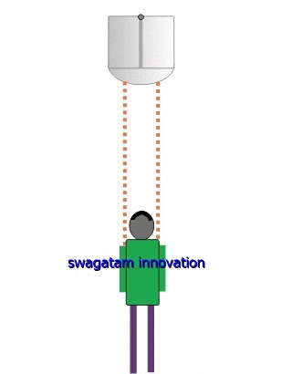
Here we can see how an oscillating PIR adapts to the issue and transforms itself enabling the detection of even static IR subjects.
This becomes possible because through its movement the PIR module transforms the stationary IR source into a continuously changing IR imaging across its two receiving slots.
Although the idea looks complex, it can be actually simply solved using a slow oscillating PwM controlled motor circuit.
We'll learn the entire mechanism and the circuit details in the following sections.
As we already discussed, conventional PIR modules are able to detect only moving living objects and cannot identify a stationary target which makes its application limited as a human motion detector only.
For applications where the detection of motiolesss human occupancy becomes necessary in such scenarios a conventional PIR can become useless, and might require some external arrangement for upgrading itself.
Designing PIR to Detect Motionless Targets
In the above section I have explained that instead of needing the target to be in motion, the PIR module can be itself be moved over a given radius for implementing the desired static target detection.
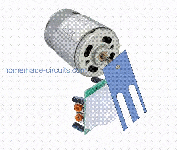
In the following sections I have explained regarding a simple circuit mechanism which can be used with a PIR mounted over a small DC motor for the proposed oscillations.
The PWM/Flip Flop Controlled Motor Driver
The system basically requires a PWM controlled speed determination and a flip flop changeover for the motor. The following diagram shows how these features can be attributed to the PIR motor with the help of a simple circuit:

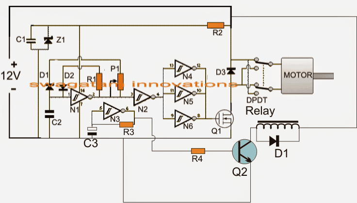
The shown circuit utilizes a single IC HEF40106 hex inverting schmitt gate IC which includes 6 inverter NOT gates.
Gates N1 and N2 are configured to produce an adjustable PWM output which is fed to the gates N4, N5, N6 forming the buffers.
The common output from these buffer gates is terminated to the gate of a motor driver mosfet.
The PWM content is set with the help of P1, which is finally applied to the connected motor via a set of DPDT relay contacts.
These relay contacts determine the direction of the motor movement (clockwise or anticlockwise).
This flip flop DPDT relay contacts is controlled by an astable timer configured around the gate N3, wherein the capacitor C3/R3 determines at what rate the relay needs to changeover in order to allow the motor to change its rotational direction consistently.
The above design allows the motor to execute the required slow to and fro oscillating movement across a given radial zone.
C3 may be selected to initiate the changeover after every 5 to 6 seconds, and the PWm may be adjusted to enable an extremely sluggish motor movement, because it just needs to ensure that the slots of the PIR cross over the IR signals of the target in a timely manner.
However since the motor operation is slow, the output from the PIR will need to be sustained through a delay OFF timer so that the connected load does not switch OFF and ON while the motor movement alternately cuts through the IR lines from the human occupancy.
The Delay Timer
The following delay timer circuit stage can be used which makes sure that each time the PIR output produces the sensed pulse, the delay from the timer is extended for 5 to 10 seconds and the connected load is never interrupted during the process.

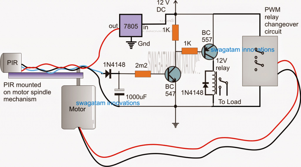
In the above set up we can see the motor which receives its electrical drive supply from the PWM/flip flop stage as discussed in the previous paragraph.
The spindle of the motor can be seen coupled with a horizontal shaft over which the PIR is clamped, such that when the motor moves, the PIR goes through a correspondingly changing radial to and fro motion.
While the above PIR motion is induced, the IR signals from a stationary target in the zone is detected in the form of short alternate pulses, which are generated at the output pin of the PIR indicated with the blue wire.
These pulses are applied across the 1000uF capacitor which charges up with each pulse and makes sure that the BC547 is kept in the conducting mode without an interruption during the process.
The relay driver comprising of the BC557 stage responds to the above stable signal from the BC547 collector and in turn keeps the relay ON, as long as the PIR keeps detecting a human presence.
The relay load thus stays activated continuously due to presence of a stationary human being in the area.
However in case the human occupancy is removed or when the target moves away from the zone, the delay timer stage keeps the relay and the load activated for the stipulated 5 to 10 seconds after which it shuts off permanently, until the zone is yet again captured by a potential IR emanating source.
Parts List
- R1, R4 = 10K
- R2 = 47 OHMS
- P1 = 100K POT
- D1, D2 = 1N4148
- D3 = MUR1560
- C1,C2 = 0.1uF/100V
- Z1 = 15V, 1/2 WATT
- Q1 = IRF540
- Q2 = BC547
- N1---N6 = IC MM74C14
- DPDT = DPST SWITCH OR DPDT RELAY
- R3, C3 to be determined by some trial and error
UPDATE:
The above explained PIR circuit for detecting static human presence can be much simplified by employing a signal chopper circuit as depicted in the following GIF simulation:
A careful inspection shows that actually an oscillatory movement is simply not required, the motor and the chopper blade could be allowed to rotate freely by keeping the motor speed at a lower level.
This would also effectively accomplish the intended static PIR sensing operation.

Video Demo proving the static human detection for a PIR
