In this post I am going to explain the datasheet of PIR or Pyroelectric Infrared Radial Sensor HC-SR501. We will understand for what purpose PIR sensor is used? Its basic trigger operations, pin connection details, technical specifications and finally we will be looking at some real life applications.
We will begin by understanding the actual PIR sensor unit which are installed inside standard PIR modules and learn its internal characteristics, pinout details and internal working details.
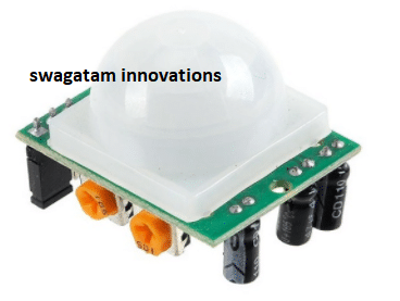
What is a PIR Sensor?
PIR stands for Pyroelectic Infrared Radial Sensor or Passive Infrared Sensor. PIR is an electronic sensor which detects the changes in the infrared light across certain distance and gives out an electrical signal at its output in response to a detected IR signal. It can detect any infrared emitting object such as human beings or animals if it is the range of the sensor, or moves away from the range, or moves within the range of the sensor.
The PIR sensor module can be divided in to two parts an infrared sensitive crystal and the processing circuit.
Illustration of PIR sensitive crystal:
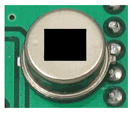
The dark portion of the metal where the IR sensitive crystal is housed, the sensitive crystal can detect the level of infrared in the surroundings. It actually houses two pyroelectic sensors for detecting moving objects. If one of the sensitive crystals detects change in infrared (increment or decrement) than the other sensitive crystal, the output gets triggered.
A dome shaped plastic structure is normally placed over this sensitive crystal which acts as lens to focus the infrared light on the sensors.
How PIR Works
The sensing operation of a pyroelectric infrared sensor is based on the property or characteristic which becomes responsible for altering the polarization of its material in response to temperature changes.
These sensors employ a dual or a pair of sensing elements for sensing the IR signals in two steps, which ensures a foolproof detection by cancelling the unwanted temperature variations within the existing EMI stage. This two-step sensing process improves the overall stability of the sensor and helps to detect IR signals only from human presence.
When a human being or a relevant IR source moves past a PIR sensor, the radiation cuts into the pair of sensing elements in an alternate manner, triggering the output to generate a pair of ON/OFF or high and low pulses, as depicted in the following waveform:
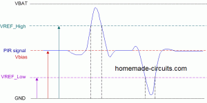
The following rough Gif simulation shows how a PIR sensor responds to a moving human and develops a couple of short sharp pulses across its output leads for the required processing or triggering an appropriately configured relay stage

Internal Layout of a PIR
The following figure shows the internal layout or the configuration inside a standard PIR sensor.
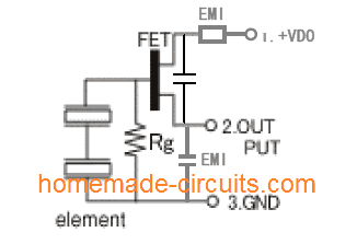
On the left we can see a pair of IR sensing elements connected in series. The upper end of this series is connected with the gate of an in-built FET which acts as a small IR signal amplifier. The Rg pull down resistor provides the required standby zero logic to the FET to makes sure that it stays completely switched OFF in the absence of an IR signal.
When a moving IR signal is detected by the pair of sensing elements, it generates a corresponding pair of hi and low logic signals as discussed above:
These pulses are appropriately amplified by the FET and replicated at its output pin for further processing by an attached circuitry.
The associated EMI stages along with the capacitor provide extra filtration to the process, in order to produce a clean set of pulses at the indicated output pin of the PIR.
Testing Set Up for the PIR Sensor
The following image shows a standard PIR sensor test set up. The output and Vss pins (negative pin) of the PIR is connected with an external pull down resistor, the Vdd pin is supplied with a 5V supply.
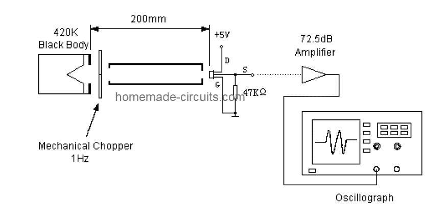
A stationery black body generates the required equivalent infrared radiation for the PIR sensor through a chopper mechanism. The chopper plate alternately cuts the IR signals imitating a moving IR target.
This chopped IR signal hits the PIR sensor generating the specified pulses across its output pin, which is suitably amplified through an opamp for analysis on a scope.
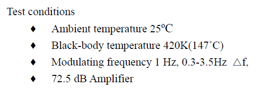
The Ideal Test Conditions for the above set up can be seen below:
Balancing the Sensing Element output
Since a dual sensing mechanism is employed in PIRs, it becomes necessary to ensure that the processing through the pair of lenses is correctly balanced.
The sensing elements are tested and appropriately configured by evaluating the respective single signal output voltage (SSOV) through the following formula:
Balance: |Va – Vb| / (Va + Vb) x 100%
Where, Va = Sensitivity of side A (mV peak to peak)
Vb = Sensitivity side B (mV peak to peak)
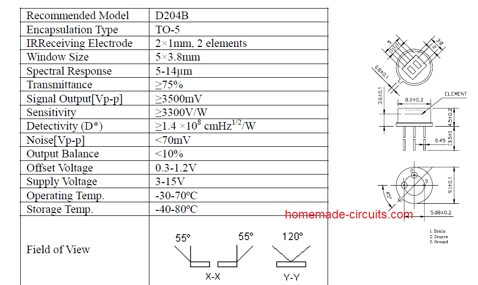
Main Specifications
The main technical specifications and dimension parameters of a PIR sensor can be learned from the following details:
Using PIR Inside Modules
Today you will find PIR modules having a PIR sensor integrated with specialized processing circuit and lens. This enhances the performance of the PIR many folds and allows the end user to get well defined optimized, amplified output from the module.
This output now only needs to be configured with a relay stage for the required ON/OFF switching of a load in response to a human presence across the stipulated zone.
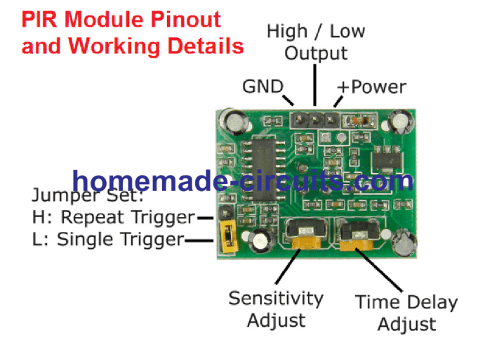
The circuit inside standard modules consist of IC BISS0001 which is specifically designed for motion detection applications. Two knobs are provided, one for adjusting the sensitivity of the module and another knob is for adjusting the time length for how long the output should stay HIGH after the module is triggered.

Now let’s investigate the technical details of the PIR sensor HC-SR501.
Operating Voltage:
The HC-SR501 is from 5 V to 20 V, which makes great flexibility for circuit designers.
Current consumption:
The HC-SR501 is a battery friendly device; its current consumption is 65 mA when it detects any change in IR light.
Output Voltage:
When the module detects a motion of infrared the output goes HIGH at 3.3 V, if the module detects no motion it goes LOW or 0 V after a fixed period.
Delay time:
A knob is provided to adjust the time for the output to stay HIGH after detecting the IR. This is time period can be adjusted from 5 seconds to 5 minute.
Sensitivity Range:
The angle of the detection area is around 110 degree cone. A knob is given to adjust the sensitivity; we can vary from 3 meter to 7 meters perpendicular to senor. The sensitivity reduces as we move either sides of the sensor.
Operating Temperature:
The HC-SR501 has an impressive operating temperature ranging from -15 to +70 degree Celsius.
Quiescent current:
The Quiescent current is the current consumed from the supply, when the sensor is not detecting any motion or when it is in idle. It consumes less than 50 uA, which makes the sensor battery friendly.
Trigger modes:
The PIR module has two trigger modes: Single trigger / non-repeat mode and repeat trigger. These two modes can be access by changing the jumper position given in the module.
Single Trigger Mode / Non-repeat Mode:
When the PIR sensor is set in single trigger mode (and the timer knob / delay time is set for 5 seconds (say)), when a human is detected the output turns HIGH for 5 seconds and turns LOW.
Repeat Trigger Mode:
When the PIR sensor is set in repeat trigger mode, when a human is detected the output turns HIGH the timer counts for 5 seconds, but when another human is detected with in those 5 seconds the timer reset to zero and counts another 5 seconds after 2nd human is detected.
Block Time:
The block time is the time interval where the sensor is disabled or will not detect motion. The block time for HC-
SR501 is 3 seconds by default.
This occurs after the delay time (which was set by timer knob) the output goes LOW for 3 seconds; during this interval no motion will be detected. After the 3 seconds (LOW) the sensor will be ready to detect motion again.
In other words, when the sensor detects motion the output goes HIGH, the output remains HIGH as per the timer knob (say 5 seconds), after 5 seconds the PIR sensor goes LOW, the LOW signal will remain for 3 seconds regardless of the new motion if any.
Dimensions of the module:
The sensor is compact enough to hide from people’s view so that it won’t affect decorates etc. It measures 32 mm x 24 mm.
Lens Size:
The white dome structure which encloses the pyroelectric sensor is called Fresnel lenses, which increase the detection range and it looks opaque. It measures 23 mm in diameter.
Applications:
• Security systems.
• Automatic lights.
• Industrial Automaton Control.
• Automatic doors.
You can find some of the projects using PIR sensor in this site.
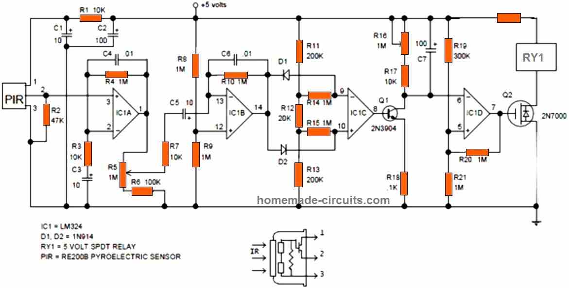
Typical PIR Module Internal Circuit Diagram
For enthusiasts who intend to build the complete PIR module along with the sensor and a full fledged amplifier, the following standard PIR schematic can be employed and used for any relevant PIR sensor based application triggering.
Have further doubts or questions? Please feel free to put them forth through the below given comment box