In this post I have explained how to construct a police, ambulance or a fire truck siren circuit using evergreen IC 555 timer and we will also learn how to build a revolving beacon light without any mechanical parts. The proposed project is divided into two parts the siren circuit and the rotating beacon light, but before dive in to the details let’s answer a very simple question.
Why do Emergency Vehicles have Sirens and a Rotating Beacon Light?
The purpose of siren and rotating lights on emergency vehicles are to convey the urgency of the journey to the commuters on the road and the traffic ahead.
They provide visual and auditory signals to vehicles on the road within a range so that non-emergency vehicles can give way to the emergency vehicles.
Only emergency vehicles and vehicles of VIP govt. officials are granted permission to install siren and beacon lights and this law may differ from country to country.
Now let’s see how we can build a two tone siren as a hobby / science fair project.
Circuit Diagram of Two Tone Siren:


The above shown circuit can generate two different tones whose generated sound resembles an emergency vehicle’s siren, such as police siren or ambulance siren. Let’s see in detail how we achieved two tone output.
There are two IC 555s deployed in the circuit and they are configured as astable multivibrator. The IC 555 on the left hand side controls a speaker and it is tuned to generate frequency in the range of KHz. The IC 555 on the right hand side produces frequency in the range from 0.5Hz to 6Hz.
To achieve two different tones from the speaker we need to alter the frequency of IC 555 present at left hand side, this is done by applying a voltage at pin #5 which is called a “control pin”.
By applying a voltage level at pin #5 of IC 555 we can achieve a frequency output that is altered from its original. Here a 10K resistor is connected so that we can get a second tone that is pleasant and resembles a siren. Readers may experiment with different resistor values to get different tones.
We can see a diode is connected with 10K resistor in series so that only +Ve input enters pin #5. Please note that negative input will also alter the speaker frequency (tone) but we found it to be unpleasant in our practical setup.
We provided a 100K potentiometer to adjust the speed of the siren at which the two frequency switches.
You may use any 8 ohm speaker (or with any other impedance value) or use a piezo speaker. The speaker is driven by a low power NPN transistor which amplifies the feeble signal from IC 555. A 10K base resistor is connected to limit the current to the transistor.
The whole police/ambulance siren circuit setup can be powered using any general purpose 9V battery.
Note: Please don’t skip any 0.1uF value capacitors that are connected to pin #5 of IC 555, they provide good stability to the generated frequencies and hence stable audio output.
This concludes about the two tone siren sound generator. Now let’s see about the rotating beacon light.
Rotating Beacon Light:
Rotating beacon lights or revolving police lights are installed on the roof of emergency vehicles and they rotate with the help of small DC motors at the same time the bulbs get powered too.
They do a good job of alerting the commuters that an emergency vehicle is approaching, but they have their disadvantages just like any (electro) mechanical devices suffers from, that is wear and tear due to friction and since they rotate 360 degrees and need for conducting electricity to the bulbs, over time they build contact resistance which could reduce the brightness, develop mechanical jams, etc. (some beacons have stationary bulb and rotating reflectors).
We can overcome all the mechanical related issues with a solid state rotating beacon light, meaning they don’t have any mechanical parts. One such design is shown below.


NOTE: Please note that the LED terminal that is connected to +9V is anode.
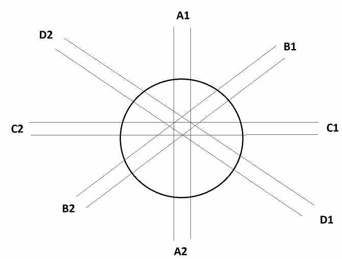
The above circuit has 8 LED arrays, only four arrays are shown for drawing convenience and showing all the LED arrays are difficult. The LED arrays are named as follows: A1, A2, B1, B2, C1, C2, D1 and D2.
A1 and A2 lights up simultaneously and they are placed on opposite sides of the dome, similarly for B1 and B2, C1 and C2, D1 and D2. There are 4 LEDs in each array and you may increase the number by connecting more LEDs with current limiting resistors.
The LEDs in the dome flashes in this sequence (A1, A2), (B1, B2), (C1, C2) and (D1, D2) this will give us an illusion of revolving lights and with a proper light diffuser on the dome spreads out the light evenly and projects more realistic rotating effect.
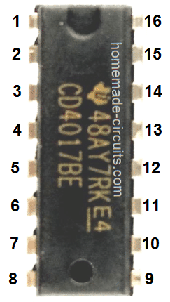
The sequential flashing of lights is achieved by using a Johnson decade counter IC 4017 which can count from 0 to 9 or output electrical signal in a determined sequence. To understand the circuit better we need to understand IC 4017’s pin diagram.
Pin Diagram of IC 4017:

- Power supply: Pin #16 is Vcc and pin #8 is GND and can operate from 5V to 18V maximum.
- Sequential output pins: Pins 3, 2, 4, 7, 10, 1, 5, 6, 9 and 11 (Q0 to Q9) are output pins whose output turns HIGH with every successive clock input it receives (one pin at an instant and rest stay LOW).
- Pin 15: Reset, when this pin is turned high, the count of the IC gets reset. During normal operation this pin will be pulled to GND.
- Pin 14: Clock input, this pin receives clock input from an external source.
- Pin 13: Clock enable, if you make this pin HIGH, any clock pulse applied at pin 14 will be ignored by the IC. During normal operation pin 13 is pulled to GND.
- Pin 12: Carry out; this pin is utilized for cascading IC 4017.
In the circuit diagram the outputs are wired according to the sequential outputs mentioned before, but we have terminated the count at 5th output (Q4) by connecting the reset pin #15 to pin #10, as we only need four sequential outputs and rest of the output stays unused.
Each output is connected to a low power NPN transistor to amplify IC’s output so that we can draw more current for the LEDs (load under 500 mA per array).
Astable Circuit
To make the circuit flash / rotate, we need a clock source, the source can be any astable multivibrator and one such multivibrator is shown below using IC 555.

The above circuit operates at 9V, the same as IC 4017 stage. The above circuit can generate frequency from 0.5 Hz to 6 Hz and the output can be adjusted using the 100K potentiometer. The frequency of this astable multivibrator will determine the speed of the rotating light. This concludes the project.
Good day Mr Swag. Please pardon me for asking this below question here as I can not find the related atticle.
Please I need a circuit that I can use to boost 3.7v lion battery to 12.6v this is to enable power my LED bulb 12volt, so that I can still charge the battery via 5volt charger.
Thanks you sir.
Godspower, there are plenty of related articles that you can select from:
https://www.homemade-circuits.com/?s=boost+converter
A1 and A2 lights up simultaneously and they are placed on opposite sides of the dome, similarly for B1 and B2, C1 and C2, D1 and D2.
But A1 and A2 go sequentially according to connections, am I right?
A!, A2 are connected one after the other, next is B1, B2 connected one after the other, and so on. Two LED columns are supposed to illuminate together to ensure better light output
This new age pictorial your using, replacing accepted Schematic Diagrams is not an improvement.