
If you are looking for current shunt monitors or current sense amplifiers then you have landed at the right page.
Current shunt monitor is an instrumentation amplifier which senses the current across a shunt resistor in a system, and converts it into a logical signal output for triggering a switching device such a relay, transistor or an SCR.
The switching device is used to either to cut off, or shut down the cause of the rising current across the shunt resistor, thereby ensuring protection to the device which is being monitored by the sensing amplifier.
Why we need the current sensing and where we can use the current shunt monitors:
- Power Management in DC-DC Converters and low dropout (LDO) voltage regulators
- Notebook, tablets, and other communication devices.
- Electric Vehicles
- Battery Chargers to monitor the charging and discharging.
- To adjust the correct Solenoid Positioning in Circuits
- To monitor the power requirements of Motor and control the speed in Motor Control system.
- Sense the current to protect an abnormal sudden surge of current in system, which may damage the system.
- Sense the current flow and measure the wattage via watt meter.
Whether you are a hobbyist, electrician, student, or a professional engineer the “NCS21xR and NCV21xR” family of ICs from ON Semiconductor are the best solution for you.
These are the voltage output and current shunt monitors which can monitor the voltages across the shunt resistor.
Regardless of the power supply, NCS21 op amp can measure the voltage from -0.3 to 26V at common mode. To measure or sense the current in a circuit you have two options:
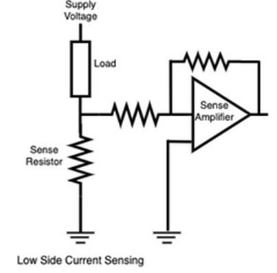
Low side sensing is easiest and inexpensive technique where you can connect a simple operational amplifier.
The current sensing circuit can be connected between the load and ground. In discrete operational amplifiers (Op Amp) connecting the shunt with ground may introduce the noise, but this issue is resolved in NCS21xR.
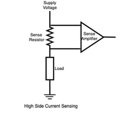
While in high side current sensing, the monitor circuit should be connected between the supply and load.
The NCS21xR IC is very helpful for sensing current from both, high side and low side techniques.
The NCS21xR ICs series are high sensitivity current shunt monitors, which can be used for accurate current sensing applications.
Salient Features:
Some key features of NCS21xR and NCV ICs are following:
- Operating Voltages +2.2V to +26V
- Very diverse range of operating temperature (-40°C to +125°C)
- Current Consumption 40µA to 80µA best suitable IC for battery operated devices (sensors, notebook etc.)
- A good dynamic range of rail-to-rail output (RRO) for amplifier to work on signals.
- Low offset drift (0.5 µ V/°C) make it ideal a variety of precision and portable applications.
- Requires very low offset voltage ±35 µ V at input to cause the output to be 0.
PIN functionalities and Configuration:
The NCS21xR and NVC21xR ICs are available in two configuration packages, SC70-6 and UQFN10 as shown in the picture.
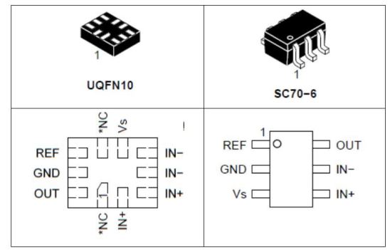
IN- and IN+ pins are to be connected across the shunt resistor in the circuit. Vs and GND pins are for power supply to the IC for operation.
OUT pin is designated for the output signal from the amplifier.
REF pin is to be connected with ground in unidirectional operation and in bidirectional operation REF should be connected with voltage reference circuit.
How to select Shunt resistor:
The selection of shunt resistor is the key factor to get the precise current measurement.
The accuracy of current measurement depends on the size and value of shunt resistor.
If you select the larger value of resistor you may get the more accurate measurement, but the larger resistance could introduce the current losses.
It is recommended by the manufacturer to use the four terminal resistor.
It will offer 2 terminals for current path in the circuit and two terminals for voltage detection path for amplifier to sense.
Unidirectional Operation:
In unidirectional operation the current flows only in one direction like power supplies and load current monitoring circuits. To connect the NCS21 for unidirectional operation do the following steps:
- Connect the shunt resistance and load power supply to the differential input pins of the IC.
- Connect the REF pin with ground.
- Provide power supply for IC through Vs and GND pin. IC can be powered from separate power supply or the same power supply of the load.
- If you want to detect short circuit current on load power supply, then use the separate power supply for the IC.
Output 1: If REF pin is grounded and there is no current passing through shunt resistance, then output of the NCS21xR will be within 50mV.
Output 2: When there is current passing through shunt resistance, the output will be up to 200mV of the applied supply voltage VS.
Bi-Directional Operation:
In bi-directional current shunt monitor, the circuit operates at both negative and positive common mode voltages.
Bi-directional Current shunt monitor circuits are used in battery charging system to detect the current in both direction (during charging and discharging).
The output in bi-directional operation varies between negative and positive voltages around a bias voltage applied at REF pin. For bidirectional operation the pins of NCDS21xR should be connected as follows:
- Connect the shunt resistance and load power supply to the differential input pins (IN- and IN+) of the IC
- Voltage reference circuit shall be connected to REF pin, the circuit must be low impedance.
- REF pin can be connected in series or shunt to voltage reference or directly to any voltage supply.
- Provide power supply for IC through Vs and GND pin.
Output: If the voltage exceeds the voltage (Vs+0.3V) at REF pin, then it will forward bias the diode connected between the pins REF and Vs.
Filtering of input and output:
The filtering of input and output signal is very important for communication devices and circuits.
The input differential signals at common mode voltage can be amplified during the high side sensing.
The devices may amplify the small voltages and noise at very high level across the shunt, which may result in an error in current measurement.
To improve the accuracy of measurement it is necessary to filter the input path of the current sensing.
The implementation of filters can be done by adding the filter resistor as shown in figure.
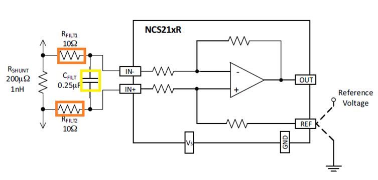
The wrong selection of filter resistor may lead to inaccurate gain. It is recommended that the value of input resistor should less than or equal to 10Ω.
A capacitor can be added to match the time constant of shunt resistor. To filter a high frequency noise, the value of capacitor should be increased to a value that delivers the required filtering.
Transients Exceeding 30 Volts:
NCS21xR offers the capability to design the circuit for the applications having transient common mode voltages more than 30 volts.
A Zener diode or transient voltage suppression (TVS) diodes can be placed with external input resistor of 10Ω. You have two options to fix the diodes:
Option one: Fix a single TVS diode with two diodes across the amplifier as highlighted green in below figure:
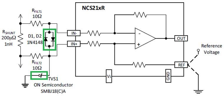
Option 2: Add to TVS diodes as highlighted blue in the below figure
Shutting down the NCS21xR:
A logic gate or MOSFET power switch, or a transistor latching can be configured with the OUT pin of the NCS21xR to switch off the power to the IC, and safeguard the associated circuitry from the detected over current situation.