A pressure switch is a device which can be used for detecting water pressure in a tank and operate a water pump motor when the pressure gets too low, or the water in the tank goes lower than a desired minimum level.
In this post I have explained a water pressure controller circuit for maintaining water supply at an optimal pressure for an entire apartment.
The design concept was requested by one of the avid readers of this blog Mr. Jorge Lazcano , The details can be studied from the following data:
Main Requirement: Circuit board to alternate and combine operation of 3 pumps
I am installing 3 pumps of equal capacity in parallel intended to provide pressure to my building. The pumps will deliver water to a pressure tank and there will be 3 pressure switches to control the system:
1st pressure switch: This is the “control” or “leading” pressure switch
Setting: ON at 30 PSI; OFF at 50 PSI.2nd pressure switch: This will detect if one pump is not sufficient and thus will indicate the circuit board to turn ON the 2nd pump.
Setting: ON at 28 PSI; OFF at 48 PSI.3rd pressure switch: If two pumps on can’t deliver the water needed, this will indicate the circuit board that the 3rd pump needs to turn on.
Setting: ON at 26 PSI; OFF at 46 PSI.Since the water consumption varies throughout the day. Normally one pump on will be sufficient to satisfy water needsmost of the day. But there will also be moments when one pump is not sufficient and then a second pump needs to turn on. And, when the maximum demand comes up, the 3 pumps combined are needed.
Also, to prevent excessive wear on any of the pumps, the circuit board needs to alternate to the next pump in sequence.
So this would be the sequence of operation:
LOW DEMAND:
PS 1: Turns ON; Pump 1: Turns ON (Pumps 2 and 3 rest)
PS 1: Turns OFF; Pump 1: Turns OFF (all Pumps rest)
Next cycle:
PS 1: Turns ON; Pump 2: Turns ON (Pumps 1 and 3 rest)
PS 1: Turns OFF; Pump 2: Turns OFF (all Pumps rest)
Next cycle:
PS 1: Turns ON; Pump 3: Turns ON (Pumps 1 and 2 rest)
PS 1: Turns OFF; Pump 3: Turns OFF (all Pumps rest)MID DEMAND (when 2 pumps are needed):
PS 1 remains ON, PS 2 Turns ON: Pump1 and 2 Turn ON (Pump 3 rests)
Then cycle repeats turning on the pump that rested in the previous cycleMAX DEMAND (when 3 pumps are needed):
PS 1 remains ON, PS 2 remains ON, PS 3 Turns ON: Pump1, 2, and 3 Turn ON (no pump at rest)The power to the circuit board could come in either 115V or 230V (single phase – 60hz). So, I would like the circuit board to have its own power supply, along with other components:
1. Its own power supply: Input: 85-265VAC; Output: 12VDC-1Amp.
2. 3 relays (to activate / deactivate 3 power relay which will control the pumps)
3. Flow detection at the system discharge (to turn off the pumps if no flow is coming out for protection via flow transducer)
4. 3 input connectors (for the pressure switches).
5. Ability via jumpers to instruct the system to use 2 of the 3 pumps when putting one pump off for maintenance is needed.Can you kindly help me with a circuit board design for this application?
I’m hoping this is not too complicated for you … which I doubtThanks in advance.
Jorge
Before we discus the proposed water tank pressure controller circuit diagram, it would be important to know how a pressure switch works.
Pressure Switch
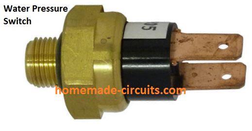
It is actually a simple electro-mechanical device which connects an internal electrical contact when the water pressure at its pressure nozzle exceeds a preset point. The internal contacts release or open when the pressure decreases below another specified lower preset point.
Optimizing Water Tank Pressure using Pressure Switch
The above pressure switch can be effectively applied for the specified requirement. The following narration describes the entire procedure.
The required water supply circuit for an apartment with sustained pressure can be visualized in the following diagram:
It fulfills the main requirement of optimizing the water supply pressure at a sustained rate by sequentially switching ON additional water pumps during low water pressure, and vice versa.
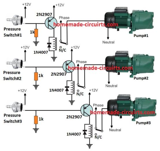
Referring to the diagram, we can see 3 identical stages wherein 3 pressure switches are configured with 3 associated relay driver stages, and the relay contacts attached with the respective 3 water pumps.
In the relay driver stage we have used a PNP transistor because the pressure switch response is normally switched OFF during low pressure and ON when the pressure reaches the maximum threshold level.
This implies that, when pressure is low the internal switch of the pressure device stays unconnected or OFF. This allows the pnp transistor to switch ON via the ground bias 1 k resistor. The relay also switches ON and initiates the motor. This basic operation is same for all the 3 motor pump stages.
Now, as per the requirement, let's assume the pressure is very low, which causes all the 3 pressure switches to disconnect its internal contacts.
As a result all the 3 motor pumps switch ON together. Due to this the water supply pressure quickly climbs and reaches the desired optimal point, which causes the pressure switch 3 and pressure 2 to switch ON. This consequently switches OFF the attached motor pump number 3 and 2.
At this point only motor 1 handles the water supply to apartment.
In case the water demand in the building suddenly increases, causes the water pressure to drop so that motor pump #1 alone becomes insufficient to fulfill the need.
The situation triggers pressure switch #2 into action, which initiates motor pump #2 for aiding the required high water pressure demand.
However, in case the water usage keeps rising and the demand is still not fulfilled by the first 2 pumps, pressure switch 3 detects this and activates motor pump #3.
The above sequential switch ON/OFF of the water pumps in response to water tank pressure variations satisfies the main basic requirement.
Motor Pump Changeover
The second requirement is shuffling the water pumps with each other so that the work pressure on motor pump 1 which is mostly switched ON can be relieved from time to time by sharing the load with motor 2.
This ensures that the working life of the motors is enhanced by reducing their wear and tear effect.
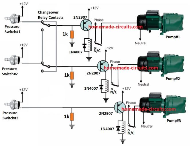
The above diagram demonstrates how this can be done through a simple changeover DPDT relay connected between the relevant pressure switches and the relay driver stages.
In this concept only two motors are considered for the changeover, the third motor is not included to avoid complexity of the design Moreover, two motor sharing seems to be quite enough to keep their wear and tear below the unsafe level.
The changeover relay does one basic job. It alternately toggles the motor #1 and motor #2 relay drivers across pressure switch #1 and #2. The time for which each motor is kept engaged for the pressurized water supply is determined by a simple IC 4060 timer as circuit as presented below:
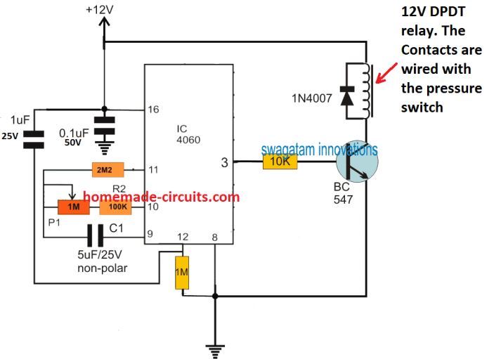
The time delay after which the changeover is initiated can be set by adjusting the 1 M pot appropriately. With some trial and error the pot resistance can be replaced with a fixed value resistor.
The power supply for all the electronic stages can be obtained from a standard 12 V 1 amp adapter.
All the relays are 12 V 30 amp relays.