
In this article I have explained the formula and techniques of configuring RC circuit networks for controlling the arcing across relay contacts while switching heavy inductive loads.
Arc suppression
An arc is produced across the contacts when a switch or a relay is opened. With time, this condition can wear down the contacts.
To overcome this problem, an Resistor/Capacitor or RC circuit is deployed across the contacts and safeguard them. Once the contacts are open, the applied voltage goes through the capacitor and not the contacts.
During the process, the capacitor charges up faster than the contacts opening time which eventually avoids an arc from forming across the contacts.
Inrush Current Suppression
When the contacts close, the inrush current from the charged capacitor and the supply voltage can be significantly higher than the ratings for the contacts thus causing them to worsen.
To prevent this, a resistor is introduced in series with the capacitor. It functions as a current limiter by absorbing the inrush current significantly thereby reducing the produced arc and extending the life of the contacts.
C.C Bates developed a formula for calculating the resistance and capacitance value that is required for the RC network: C = I2 /10, and Rc= Vo /[10I{1+(50/Vo)}]
The voltage induced at the contact opening can be determined by
V=IRc= (Rc/RL) Vo
- Where VO = Voltage source
- I = Load current at contact opening
- RC = Resistance of RC Snubber
- C = Capacitance of RC Snubber
- RL = Load Resistance
In our following examples we talk about the reed relay arcing issues, and try to evaluate the calculations required for designing RC networks across its contacts.
Since the principle of arcing may be the same in bigger relays also, the formulas used in reed relay could be also applied for dimensioning the RC networks for the bigger relays.
How Arcing Happens in Reed Relay Switching
A reed switch or reed sensor can be used for controlling an inductive device like a relay coil, solenoid, transformer, small motor etc.
When the reed switch opens, the charge stored in the inductance in the device will force the switch contacts to a high voltage. Once the switch opens, the contact gap is tiny in the beginning.
Therefore, arcing between the contact gap can happen almost immediately while the switch is just opening.
The phenomenon can occur in both resistive and inductive loads, but since the latter produce a higher voltage, increased arcing activity is seen thus reducing the switch life.
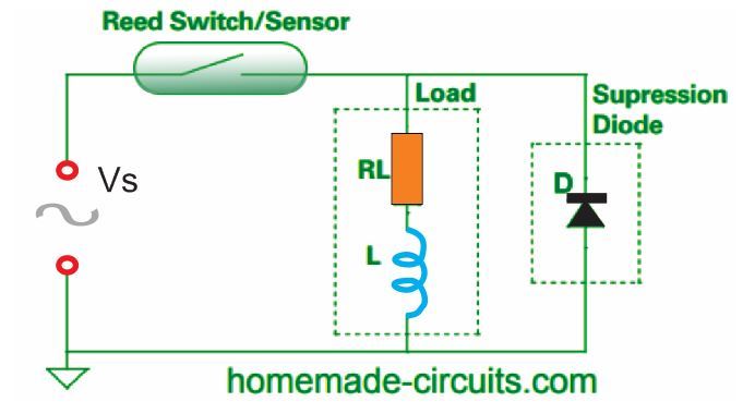
A diode is normally used by the DC inductive circuits to avoid high voltage. This type of diode is called the flyback, freewheeling, or catch diode.
Unfortunately, the application of this diode is not possible in AC circuits.
So, we must use a metal-oxide varistor (MOV), a bidirectional transient voltage suppressor (TVS) diode or an RC suppression network, also known as a snubber.
These diverse arc suppression approaches have many pros and cons. Not using suppression is also an option if the relay contact life isn't affected without it.
The many factors that determines which approach needs to be undertaken, include cost, contact life, packing etc.
The fundamental reason for spark suppression circuit designs is to minimize arcing and the noise generated when engaging relays and switches.
RC Design Considerations
Using DC supply with TVS Suppressor Diode:
Using Bidirectional TVS Diode
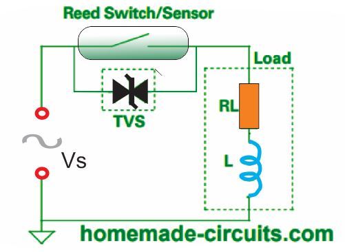
The MOV and TVS diodes conduct current when a threshold voltage is surpassed.
Normally, these diodes are connected parallel to the switch contact. Even at low voltages like 24 VAC, these devices are capable of working efficiently.
Moreover, they can also function well at higher inductance 120 VAC loads. Compared to TVS diodes, MOV devices have added capacitance.
Thus, when an MOV device is utilized, you must consider the capacitance to be used. The Hamlin application note describes this scenario better.
RC suppression had the edge because of limiting the switch contact voltage exactly during switch opening when the contact gap is small.
Furthermore, RC suppression can be implemented to lessen arcing and improve life in resistive loads.
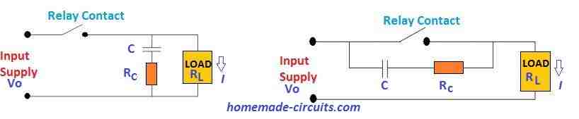
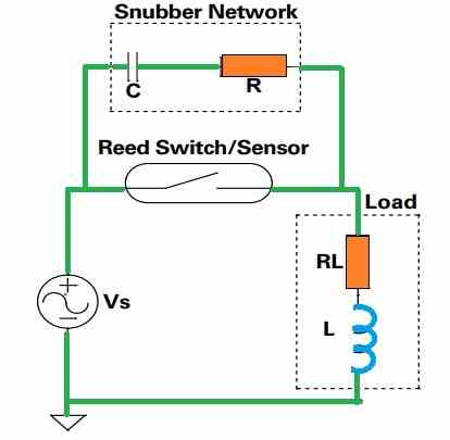
On an RC suppression circuit, a capacitor and resistor network connected in series is mounted across the switch contact in a parallel connection.
Another option is to place the capacitor and resistor across the load.
While attaching the RC snubber across the switch contact is ideal, there is a huge disadvantage because this creates a current path to the load when the switch is open.
If the snubber is installed across the load, it eliminates the current. However, changes in the connections and source impedance can affect the efficiency of the arc suppression.
Applying RC Snubber Parallel with the Switch Contact
In the snubber, the values of the resistor and the capacitor are dependent on the requirement.
The chosen resistor must have a value high enough to restrict the capacitive discharge current when the contacts of the switch close. At the same time, it must be small enough to restrict the voltage when the switch contacts open.
If you choose a large capacitor value, it will surely decrease the voltage impact while the switch contacts opens.
But larger capacitor can be expensive and might cause higher capacitive discharge energy during the time the contacts of the switch close. This type applies to both DC and AC circuits.
Using RC (Snubber) Suppression Parallel with the Load
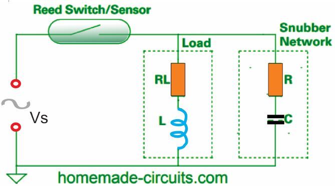
Ohm’s law is applied to choose the most appropriate resistor value for the arc suppression.
In the Ohm's law R = V/I, we apply the formula R = 0.5 (Vpk / ISW) and R = 0.3 (Vpk / ISW), where Vpk is the AC peak voltage (1.414 Vrms) and ISW is the rated switching current of the relay contact).
To decrease the contact degradation due to arcing, we have to make sure the R value is minimum. On the other hand, the R value must be increased to lessen the relay contact arcing due to the inrush current.
Determining the value of R in between these scenarios is the challenge.
You can begin with C = 0.1μF or 100 nF, when selecting the capacitor because this is standard value and thus cost-friendly. Depending on the performance examination of this capacitor, you can increase it until the capacitance is sufficient.
There are multiple methods to assess the performance of the chosen snubber values. Some can be performed just by calculation or simulation. However, the resistive and inductive features of the load may appear indefinite.
This is largely caused by the inductance of electromechanical loads that fluctuates when the components change positions.
It is a good practice to examine the voltage waveform across the switch contacts via an oscilloscope especially during contact opening. The snubber system should alleviate or at least minimize the arcing that happens when the contacts open and close.
The increasing voltage should not restart contact arcing. Furthermore, the maximum voltage across the capacitor in the snubber must not be more than it’s voltage rating.
Yet another way to find out if the snubber is working properly for a reed switch is to look at the switch contact gap and inspect the radiance of the light produced by the arc.
If there’s less light, that means the energy generating the arc is little and therefore warrants longer life.
The final and most precise method of examining the snubber’s performance is to conduct a life test.
Contact life is directly proportional to the number of switching cycles and not to the number of powered and unpowered hours.
It is advised to keep the maximum number of operations per second for life testing of arcing loads is around 5 to 50 operations per second.
This is around 5 to 50 Hz of maximum frequency. The number of tests you can carry out is reliant on the electrical load and the difference between convenience and precision.
When you need to find out the specifications of the components for the snubber, you must consider a few other things also apart from the described inspection of arc evaluation, highest capacitor voltage and life.
It is fundamental that when a switch contact is opened, current flows through the snubber circuit.
You must ensure that this current does not cause trouble to the snubber’s application. Moreover, it is essential to confirm that the power dissipation in the snubber’s resistor does not surpass its power rating.
One more thought is that an RC snubber circuit can be utilized in combination with a bidirectional TVS diode of MOV.
An RC snubber can be a highly efficient circuitry in limiting the initial voltage across the opening relay contacts, while the TVS or MOV may be a more efficient alternative for restricting peak surge voltages.
References:
https://www.homemade-circuits.com/wp-content/uploads/2020/10/RC-snubber.pdf
https://www.homemade-circuits.com/wp-content/uploads/2020/10/spark_suppression_compressed.pdf
https://m.littelfuse.com/~/media/electronics/application_notes/reed_switches/littelfuse_magnetic_sensors_and_reed_switches_inductive_load_arc_suppression_application_note.pdf.pdf