In this post I have explained a programmable bidirectional motor timer circuit for controlling a custom industrial mechanism. The idea was requested by Mr. Milton
Technical Specifications
I am a glass specialist, pretty good with DIY etc, but not too hot on electrics. I am planning a build for a 10mm Toughened Glass Watch display box, however our client would like this to be a watch winder box.
I have established that we require 4 x 10rpm 24V AC Motors to run simultaneously. They need to start turning every hour, for 15-20 minutes.
However, they need to turn clockwise then anti clockwise hour to hour. It would be good if I could also have a manual option to start and stop the motors when I wanted.
Is this something someone can help with? Please?
Thanks!
Milton
The Design
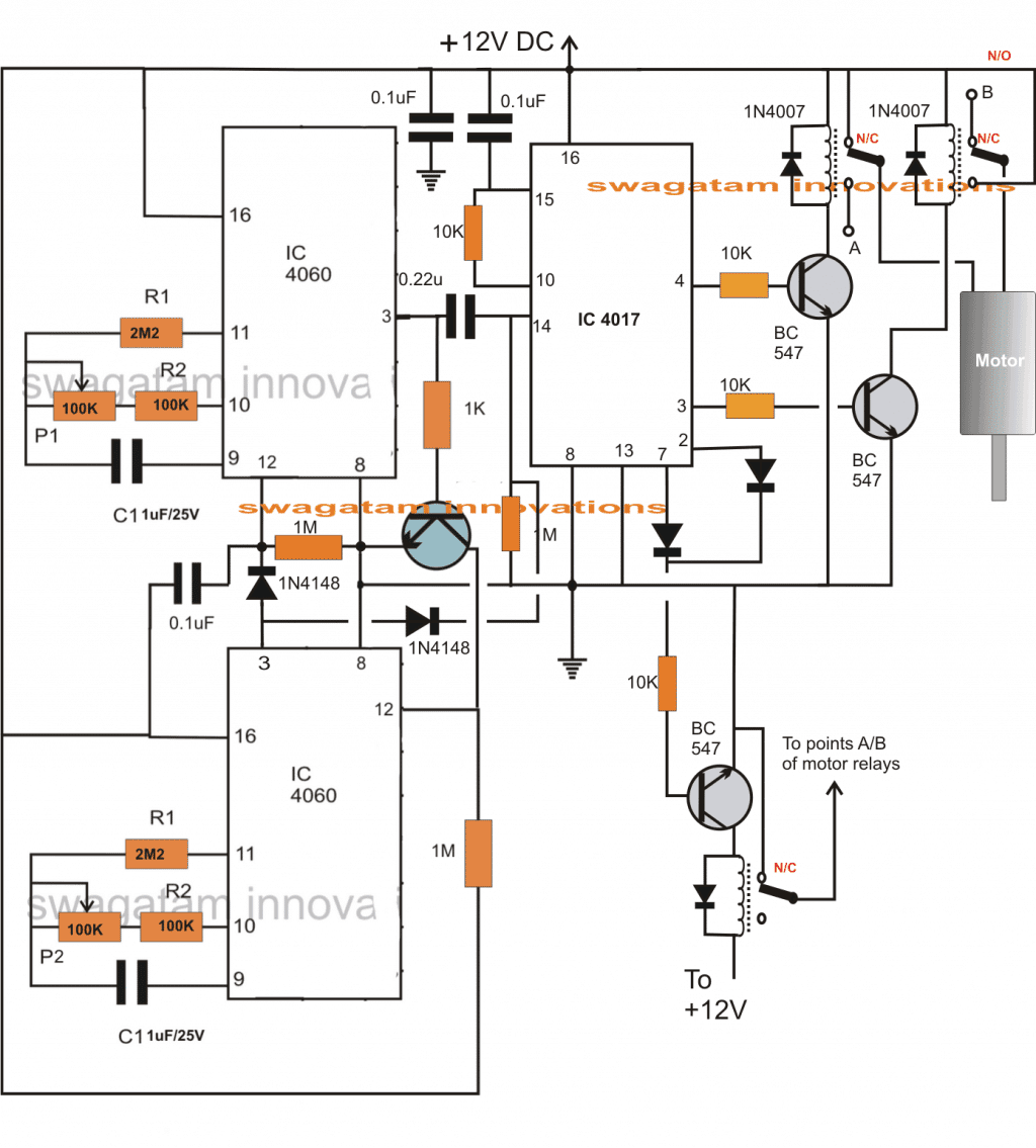
The proposed circuit can be understood with the following description:
The stage comprising the two 4060 ICs are configured as a programmable stage. The upper 4060 IC is wired as the OFF timer circuit while the lower IC decides the ON time of the circuit.
The section at the right hand side consisting of the IC 4017 forms a standard flip flop circuit which toggles its output from 3 to 2 and vice versa in response to every high trigger at its pin#14.
When power is switched ON, The upper 4060 starts counting. This stage may be set for producing a time delay of 20 minutes as per the requested specs.
At the same time pin#3 of IC4017 produces a high logic since it's the start pin of the IC4017. The connected motor now starts spinning in a particular direction depending upon its polarity with the relays.
After the set 20 minutes, the time elapses, pin#3 of the upper 4060 becomes high which initiates the lower 4060.
This high from the 4060 applies a logic high trigger at pin14 of IC4017 via the 0.22uF capacitor which forces its output to hop from pin3 to pin2.
The relay at pin2/7 driver stage now activates cutting off the motor supply and thus halting the motor.
After about 1 hour which should be the specified interval set with the lower IC 4060, its pin#3 goes high and instantly resets the upper IC4060 so that it reverts to it previous mode.
In the process, it also toggles the IC4017 so that its output shifts from pin2 to pin4, the relay at pin4 gets restored and the motor starts rotating but now in the opposite direction.
The motor keeps rotating until the next 20 minutes after which as above the sequence of IC 4017 jumps to pin7 and the motor halts again.
With the later subsequent trigger from the lower 4060 IC, the system reverts to its initial situation and the cycle goes on repeating as proposed in the request.
Circuit Diagram
