The following article discusses a temperature controller circuit which can be used for controlling the temperature inside reptile racks. The idea was requested by Mr. Tom.
Technical Specifications
I'm looking to make a circuit to use to heat my reptile rack, I really like your incubator circuit, but do not have the electronics expertise to change it to suit my needs, this is were this email comes in.
I need to control a 240V 600w heating element, using an external probe.
The temperature control range can be quite small, as I'll only need it to control to 30 degree Celsius during the day and drop to 21 degrees during the night, I have been looking at using two separate stats and have one for daytime and one for nighttime, switching them over with a mechanical time switch. but there has to be a better way.
One thing I have been told is because I plan to use it with reptiles I would need it to fail in a safe state, so to avoid any burns etc, if the stat was to short out it would switch the output off rather than being stuck on. Is there a simple way of doing this?
Basically I would need the temperature to go up in the morning say about 8.00am to 30 degrees, then control at 30 all day until around 6pm and start to drop off so that it reaches 21 degree's at around 20.00pm, then continue controlling all night.
In order to stimulate feeding and breeding there needs to be a slow temperature change more so at night than in the morning, as they are nocturnal.
If it would be possible to increase/decrease the length of the day as well, so in the summer its a 12 hour day then drop down slowly over a few weeks to 8 hour days, it would be better than any stat on the market, but as you say it would become more complex and difficult to set.
This is the part I was thinking if you could use a mechanical timer plug to input when you want day temperatures.
I hope this is clearer
Thanks againTOM
The Design
The above requirement basically involves two stages, the first being the timing stage, and the other temperature controller stage.
The circuit would therefore essentially comprise of the these two stages, lets learn the functioning with the following points:
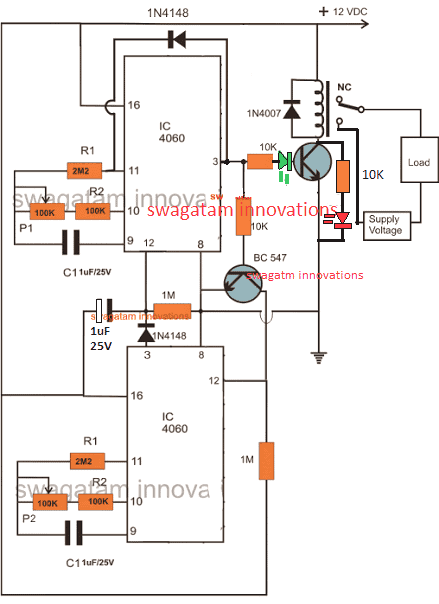
The diagrams given below together function as the proposed reptile rack programmable temperature controller circuit.
The first diagram shows a discretely programmable timer circuit consisting of a couple of 4060 ICs. I have explained how it functions
IC1 determines the OFF time while IC2 determines the ON time of the connected relay.
The relay contacts are appropriately connected with the temperature controller stage such that it selects between the 30 degree and 21 degree temperature options by toggling itself.
P1 is adjusted such that C1 counts for the entire day while its output pin stays low, and becomes high only after the set period elapses. During this period the N/C contacts of the relay makes sure that the temperature controller is referenced to control at about 30 degree Celsius.
Once the above time lapses, T1 switches ON the relay so that it toggles to its N/O state where it selects the 21 degree option for the attached temperature controller.
At this point T2 is also switched ON which starts clocking the lower IC 4060 (IC2).
For IC2 P2 is set such that it counts for the entire night until the next morning 10 O clock, when it toggles IC1 back into action for repeating the cycle afresh.
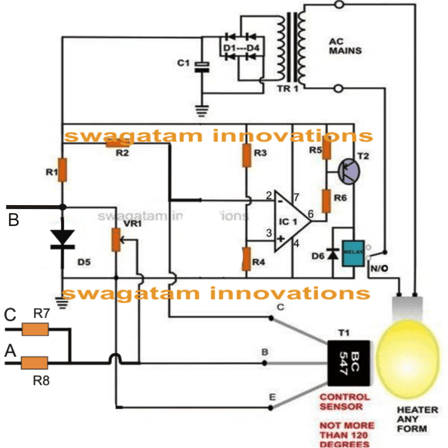
The second circuit is s simple yet accurate temperature controller circuit, it functions in the following manner:
Here D5 and T1 are bridged such that their characteristics become interlinked. Since both these devices change their conduction property in response to ambient temperature, they effectively complement each other in the discussed design.
D5 acts and clamps a reference voltage for T1 and this reference varies with the atmospheric temperature.
Depending upon this reference and the setting of VR1, T1 responds to the heat generated from the attached heating source.
With increase in the source temperature, T1 keeps conducting a little more thereby decreasing its collector potential.
IC1 which is an opamp 741 is configured as a comparator, its pin#3 is referenced at 1/2 Vcc which makes the IC functional with a single supply instead of dual.
With T1 potential going below a certain level, voltage at pin2 of IC1 drifts below the voltage at pin3, which instantly prompts the IC to change its output state. The connected relay driver stage instantly switches off itself ad the heater.
The above condition persists until the heater temperature begins falling which at some point triggers the IC back to its previous state, switching ON the heater, and the process continues.
The above process is controlled in two ranges which must be carefully set by adjusting VR1 and the proximity of T1 to the heat source.
By some trial and error VR1 must be set such that without the timer connected, and point "A" manually connected to B, the temperature is maintained at 30 degrees.
Once the above is set the lower range automatically gets adjusted since the operation is very linear, and R7 is chosen as 1/3rd of R8 (since 20 degrees is 1/3rd less to 30 degree)
To make the response even more precise and adjustable, R4 may be made variable but it might complicate the settings a bit more.

Parts List for the second circuit
R1 = 2k7,
R2, R5, R6 = 1K
R3, R4= 10K,R7 = 470 ohms
R8 = 680 ohms
D1---D4 = 1N4007,
D5, D6 = 1N4148,P1 = 100K,
VR1 = 200 Ohms, 1Watt,
VR2 = 100k potC1 = 1000uF/25V,
T1 = BC547,T2 = BC557,
IC = 741,OPTO = LED/LDR Combo.
Relay = 12 V, 400 Ohm, SPDT.
