A very interesting push button operated fan regulator circuit with LED display is explained in the following article, which can be built and installed at home for the suggested purpose. The idea was requested by Mr. Sriram KP.
The Design
Normally all fan regulators whether it's a mechanical or electronic employ a rotary kind of switch for the speed control operations. The mechanical type of fan regulators typically use a clicking type of rotary switch while the electronic ones mostly can be seen with a smoothly adjustable Pot type of control.
Although the electronic versions are more efficient than the mechanical variants, these lack the ability to display the speed levels accurately and furthermore the pot control feature looks quite outdated, technology wise.
The proposed push button fan regulator circuit with display discussed in this post utilizes PWM control for controlling the speed of the fan and enables the user to do the same using an up, down push button arrangement. Additionally the design also offers a 10 LED speed level indicator in response to the button operations.

Circuit Operation
The circuit can be understood with the following explained points:
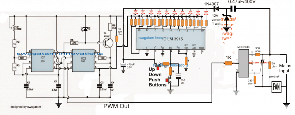
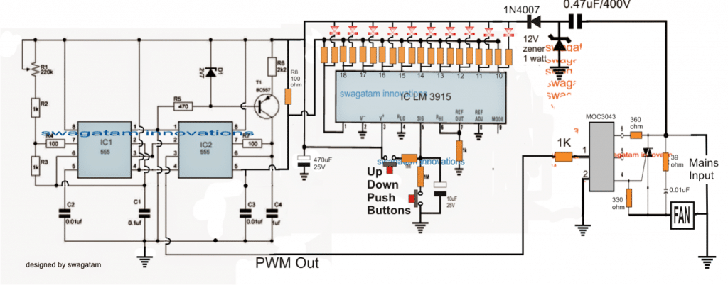
The 555 IC1 is configured as a clock generator, and the second 555 IC2 as a PWM generator circuit.
The high frequency clocks generated by IC1 is fed to pin#2 of IC2 which is used by IC2 for generating triangle waves at its pin#7
The triangle waves at pin#7 of IC2 is compared by the potential difference at its pin#5 to generate the corresponding PWMs at its pin#3.
Depending on this potential difference, the PWM output at pin#3 is adjusted into narrow pulses (for lower potentials) and wider pulses (for higher potentials).
The above potential difference at pin#5 is derived from the outputs of the IC LM3915, which is a dot/bar mode LED sequential driver IC.
Here this IC is configured as an up/down push button driver circuit. Pressing the relevant buttons enables its outputs to sequence with a logic low from pin#1 to pin#10 and vice versa.
The resistors across these outputs which are associated pin#5 of IC2 are arranged in an gradually incrementing manner from pin#10 to pin#1, such that pin#1 has the highest value resistor and pin#10 the lowest value resistor.
The highest value resistor could be a 6K8 and the lowest value could be a 100 ohm, while the other in between should gradually and proportionately selected and distributed across these values.
The LED resistors can be all 1K resistors.
Thus when one of the push buttons is arbitrarily pressed such that the output sequence moves across one of the outputs, the resistor at this output in conjunction with R8 generates a particular potential difference at pin#5 of IC2 which in turn determines the PWM width at pin#3 of IC2.
This PWM is then fed to a specialized triac driver optocoupler IC MOC3043, which reads the PWMs through its LED's average intensity and drives the connected triac accordingly rendering the corresponding amount of AC on the connected load.
The connected load here being a fan, causes the fan to rotate at the specified speed, in accordance with the fed PWM.
The LED display responds to the push button pressing and jumps across the outputs of the LM3915 in an up/down manner as long as the button is in the depressed mode, and settles down to the selected pinout as soon as the respective button is released.
Thus the LED indicates the speed level while the corresponding potential divider created at this pinout determines the PWM level at pin#3 of IC2 which is subsequently forwarded to the triac driver optocoupler.
The entire circuit of rthe above explained push button fan regulator is powered from a simple stabilized transformerless power supply using the shown 0.47uF capacitor, a 12V zener diode and a 1N4007 diode.
