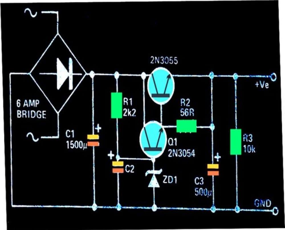
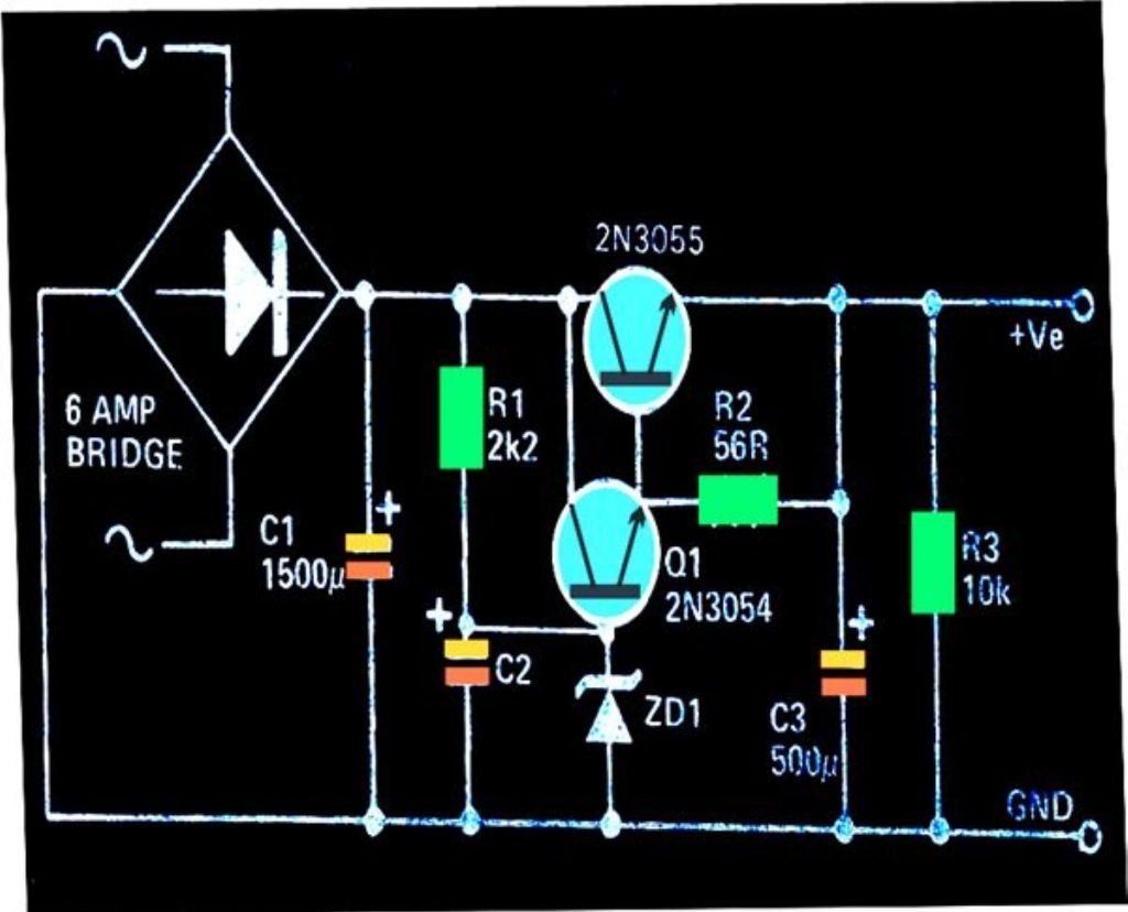
The circuit I have explained below can be used for applications that require stringent voltage regulations and ripple rejection criteria. The transistor pair are configured such that all residual ripple factor are perfectly rectified.
Circuit Operation
The circuit below shows a simple way of acquiring a perfectly regulated and stabilized high current DC voltage output using ordinary transistors.
The circuit is very simple to understand, let's study it with the following points:
This simple efficient high current 2N3055 based power supply is designed to handle in excess of 3 amp of currents, but must not exceed 5 amps.
The voltage that is required to be stabilized can be adjusted through R1 and the value of the zener diode.
The diodes at the input are arranged in a bridge network configuration for rectifying the voltage applied from the transformer.
C1 smoothens the DC further to feeds the filtered DC to the control circuit made up of Q1 and Q2.
R1 is introduced to start up the circuit by providing the required biasing to the transistor pair.
C2 makes sure that the transistor receive a perfectly smooth DC at their base without any ripples.
The zener diode at the base of the Q1 clamps the transistor with a fixed biasing voltage and inhibits any rise at the output voltage, irrespective of the voltage at the input.
Meaning even if the input voltage from the bridge network rises, the output remains unaffected and produces the voltage defined by the setting of R1 and the zener diode.

Parts List
- Resistors are 1/4 watt 1% MFR
- 2.2 k, 10 k, 56 Ω = 1 each
- Capacitors
- Electrolytic 1500 µF / 50 V = 1
- Electrolytic 500 µF / 50 v = 2
- Semiconductors
- Bridge Rectifier Diodes 6A4 = 4
- Zener Diode 1 watt, voltage value as desired between 3 V to 30 V = 1
- Transistors 2N3055, 2N3054 = 1 each
- Large finned heatsink for the above transistors = 2
- Transformer 0-15V, 5 amp = 1
