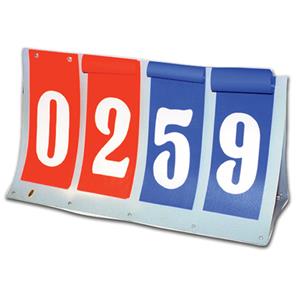
In this post I have explained how to build a simple remote controlled game scoreboard circuit with two digits for facilitating the user a hassle free changing of the digits remotely, during a game or a match. The idea was requested by Mr. Richard.
Circuit Objectives and Requirements
For our co-ed volleyball game we use manual flip cards {simple 00 to 99 (x2) flip cards}
This is awkward and time consuming, somebody needs to flip the numbers.
If I had a remote controlled display, no time would be wasted flipping numbers.
This is a recreation league with no BIG $ to spend.
Looking for a 2 digit - seven segment display (x2) with the ability to count up and count down (4 buttons)
Similar to this display -
Can I incorporate a 4 button RF transmitter/receiver
The Design
The following figure shows a simple two digit up/down pulse counter circuit which can be used for the above requested application.
The incorporation of the specific digital ICs make the design extremely straightforward to configure and operate for the desired pulse counting display.
The IC1 and IC3 form the actual counter chips, whose BCD outputs are appropriately translated into the required 7 segment digital display outputs.
Circuit Diagram
Pin#5 and pin#4 of the 74LS192 are rigged as the UP and DOWN sensing inputs, and the relevant switches when operated allow these pins to get the specified logic zero pulses for displaying the corresponding incrementing or reversing numbers on the associated 7 segment display modules.
The switch at pin#14 of the ICs is used for resetting the displays to zero with a single operation.
Since the proposed digital game scoreboard circuit is supposed to be controlled with a remote control unit, the switches at pin#5, 4 and 14 can be seen replaced with the relay contacts from the remote receiver unit.
Therefore when the compatible or matching buttons on the remote transmitter handset are pressed, the corresponding relay contacts close causing the relevant number to appear on the display board either in the ascending or descending order depending on which button was toggled.
That implies, this remote controlled game scoreboard circuit can be operated using a remote control from anywhere within the stipulated range by any member of the team simply with a press of a button of the transmitter module. And this can be done while the user enjoys the game on his/her preferred place of the ground.
The Remote Control Circuit
The remote control circuit for the discussed digital game scoreboard has been already covered in quite many articles from this website, so I won't be discussing it separately here.
The following 4 channel RF remote control circuit could be applied for the above explained circuit.
Simple RF Remote Control Circuit without Microcontroller
A little pondering reveals that the relays can be actually avoided and the output pins of the receiver RF module could be directly configured with the pin#4, 5 of the of the up/down counter IC, and the reset pin through a NPN buffer.
Alternatively, the 4 channel remote control module could be purchased ready made from the market, and in that case the existing relay contacts in the receiver unit could be wired as already suggested in this article.
The colored lines in the proposed remote controlled game scoreboard diagram indicate how two counter modules are cascaded between each other, more digits could be included by simply cascading more such IC stages in similar fashion.

