In this post I have explained how to make a cheap yet powerful remote controlled trolley which can be maneuvered left, right, forward and reverse as required, by the user using the given remote handset. The idea does not rely on an microcontroller circuit.
In one of my previous posts I discussed about a simple remote controlled toy car circuit, the present idea of a remote controlled trolley is inspired with the same concept but is intended to be used for carrying formidable and much heavier loads.
Remote Controlled Trolley for Retail Outlets
This design may be specifically suited and applicable for malls or shopping retail outlets where it may be implemented as a small transport vehicle for transporting material within the compound or the premise with the help of a few presses of the remote Tx unit.
The first step in building the proposed remote controlled trolley would be to procure a set of standard Rx/Tx RF modules either from your local electronic dealer or from any online store, I recommend buying from an online store as it would be much easier and convenient, although costlier.
The procured units would look as shown below:
Using the 433MHz Tx, Rx Modules

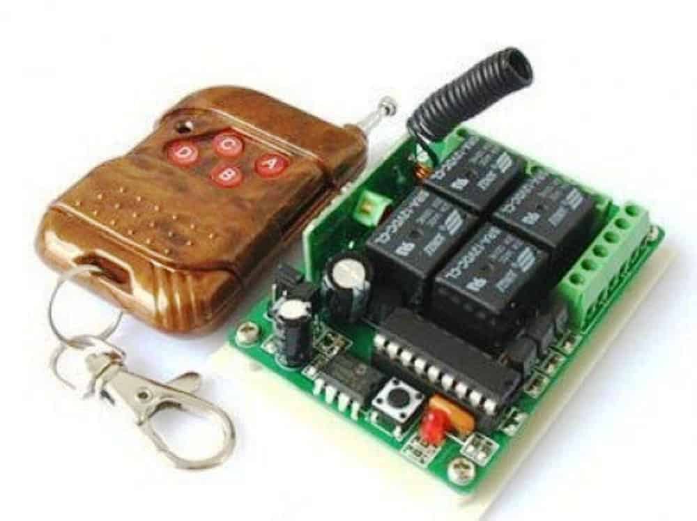
The left side brown color unit is the Tx or the transmitter unit while the adjoining circuit broad is the Rx or the receiver unit.
The Tx unit can be seen with 4 red colored buttons marked as A, B, C, D, and the Rx board may be witnessed having 4 relays (black color boxes).
The four respective buttons of the Tx module are wirelessly coupled for operating the four corresponding relays of the Rx module.
You can see connectors fixed around the edges of the board (green colored), these connectors are appropriately terminated with the (+) (-) supply inputs for the Rx board and also with the relay contacts, for all the 4 relays.
A relay, as we all know consists of 5 basic contacts and their pinouts viz: 2 pins for the coil, one for the pole and one each for the N/C and the N/O.
Since there are 4 relays in the Rx unit, you will be able to find 5 x 4 = 20 outputs associated with the relevant connector points.
It could be a tedious task to separately track down these relay terminations on the connectors, so I recommend soldering wires directly on the relay pinouts in order to save yourself from the above task, this effort will be required later while we engage the unit with the trolley's control circuit.
Building the relay control circuit for the trolley
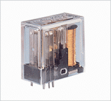
For this you will require a handful of relays and diodes. The relays should be correctly rated in order to handle the high power wheel motors of the trolley. I recommend using OEN make relays for this, as shown in the following image:
The diodes which will be required in the relay driver circuit can be our standard 1N4007 diodes.
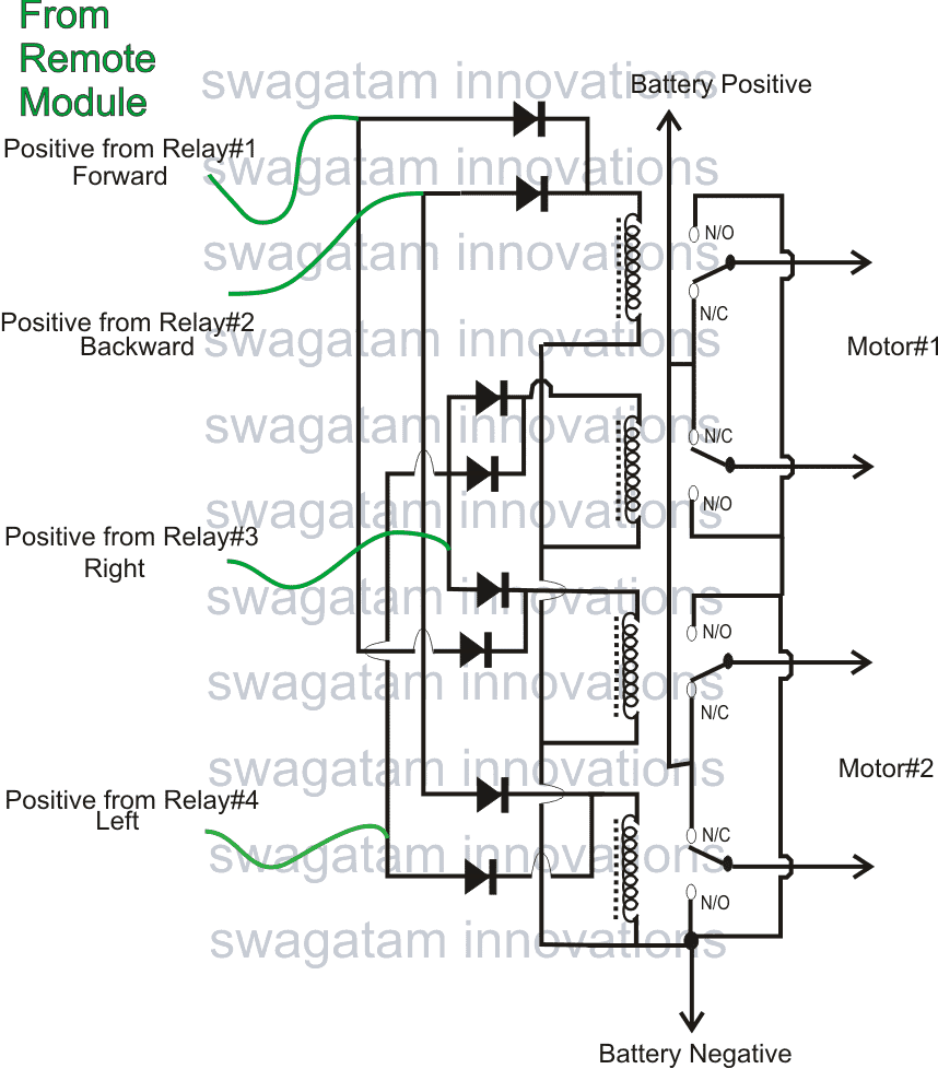
The circuit details for the same may be witnessed in the following diagram:
Relay Wiring Details and Schematic
How the Remote Trolley Circuit Works
Using the above specified relays and the diodes you will need to finish building the above relay driver circuit board which may be simply done on a piece of veroboard.
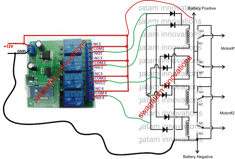
After this we have a major task at our disposal that is integrating the green wires shown in the above diagram with the remote control Rx board.
Before the integration we'll have to insert some mods in the Rx module, as I have explained below:
Using pieces of insulated wires, appropriately stripped and tinned at the ends go on connecting (by soldering) all the pole pins of the relay and link this common joint with the positive line of the Rx board.
Now in this situation we can assume that when the relays are not in an activated state (through the remote handset) the pole positive input of each relay will be linked to their respective N/C points, and when activated the positive from the pole will shift and get connected with the relevant N/O points.
In short, on activation the N/O contact will receive the positive supply and therefore we are interested in this positive supply from the N/O contacts because these will be initiated only when the relays are activated, which implies that when the Tx (transmitter) buttons are pressed.
Therefore all the relevant N/O pinouts must be joined to the green wires of the above indicated relay driver circuit.
Once this is done, the Rx will be integrated with the relay driver module for executing all the intended maneuvers of the remote controlled trolley, that is: the forward, reverse, motions and the left, right turns.
Powering the relay Driver Board
Since the relays in the relay driver stage would be responsible for moving the heavy motors connected with the trolley wheel,the supply for this would need to be equivalently strong, therefore deep cycle lead acid batteries become ideally suited for this application.
Assuming the motors to be rated at 12V, a 40AH lead acid battery would be good enough for enabling the trolley to move even with heavier loads.
Configuring the Wheels with the Motors for the Intended maneuvers
As may be identified in the following figure, the discussed remote controlled trolley will require 4 wheels for su[porting and rolling the system.
However only the front two wheels would be responsible for enabling the intended reverse, forward, right and left maneuvers, and therefore the motors would be required to be clamped with these two front wheels of the trolley, as shown in the following image:
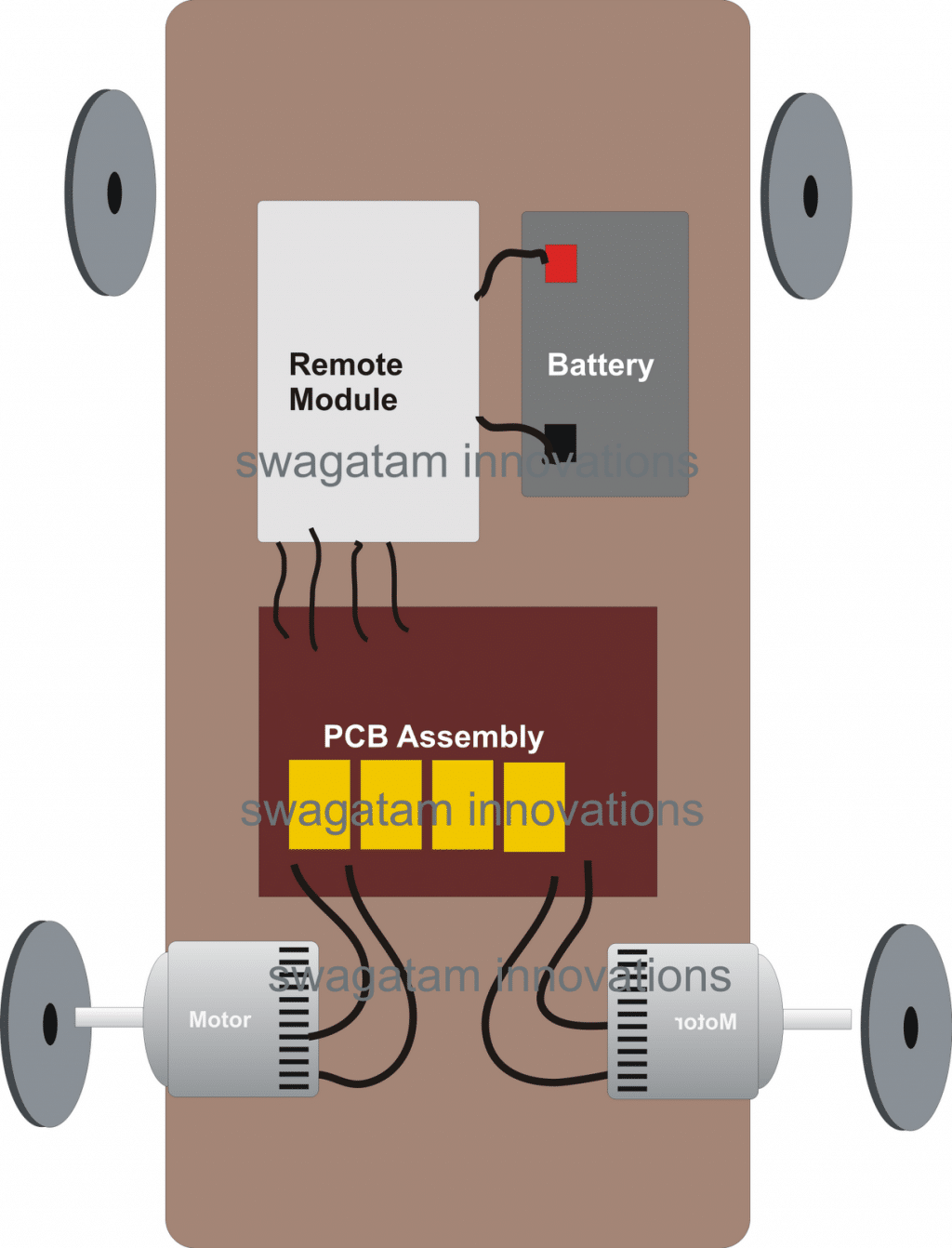
Configuring the Trolley Wheel Connections
The rear wheels are just dummy wheels, fixed only for allowing a free rolling of the trolley, in response to the front wheel commands.
As may be observed in the above image, the module marked as PCB assembly is the relay driver board, the remote module signifies the Rx remote receiver board while the battery is the 40 AH 12V battery which I have explained in the previous section of the article.
After assembling you may have to tweak and check the motor wire connections with the relay driver board.
For a forward and reverse motion both the motors must be in sync with each other, on the other hand for executing a right or a left flip, the motors must go through an opposite rotational movement.
If you find the motor not behaving in the above manner, it may be most probably corrected by simply swapping the polarity of one of the motors. This will immediately correct the situation and force the motors to implement the specified maneuvers.
Finally the A. B, C, D buttons may be appropriately matched or interchanged for the any of the respective maneuvers by tweaking the green wire links with the Rx module, as per the users personal preference.
Hello Swagatam,
I used your circuitry to build a remote controlled child’s ride on toy (Barbie Jeep) that was discarded in the trash.The intent was to chase deer away from our garden, but with halloween approaching it may be used as a scary ghost. I have a video but it is too large to post.
Thank you and best regards
Erik Hendrickson
Thanks Erik, that sounds cool!
If possible you can upload the video to your google drive, and provide the link (shared mode) to me here, will appreciate it a lot!
https://drive.google.com/file/d/1XZrGNnBO8dlODCDVGPRgcAz6B7sWH2bX/view?usp=sharing
Hello Swagatam, sorry for the late posting. See if the link works. The video is meh.
I had wanted to use the creative side of my brain to make a loud montster truck video with searing titles and graphics. That is something for more youthful creatives, like yourself.
The remote solution of yours is inexpensive (no futaba servos!!) and certainly functional although some customers have expressed concerns about reliability of the module.
Thank you and best regards. Erik H
Thanks Erik, but the link isn’t in the sharing mode, therefore I am unable to open it. Please change the link setting to “sharing mode” so that I am able to access the link.
Dear Swagatam its very helpful to have such electronics circuit guide.
Can you help me to identify IR remotes for circuit where KT27S05 relay are getting used.
Dear Prasad, a relay has nothing to do with a given module's working specifications so it cannot used an an identifying parameter.