
In this post we are going to see how we can construct an RGB LED light strip controller circuit for PC cabinets and also for general decoration purposes. In this post we will construct a couple of RGB light strip controller designs, one for a PC cabinets and one for general purpose which can be operated using any IR remote and push buttons.

RGB LED light strip overview:
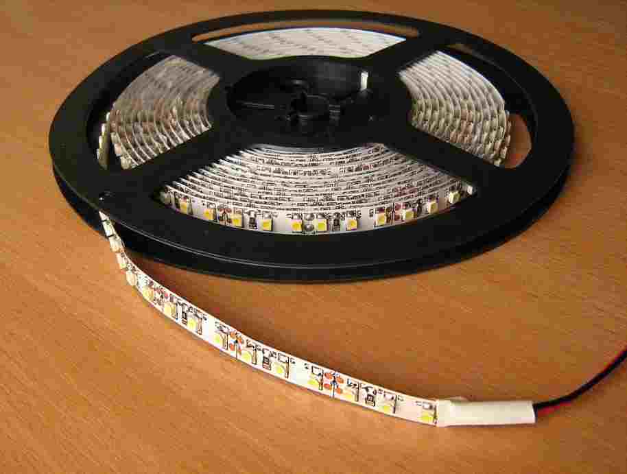
LED light strips are long flexible PCB (with sticky back) with RGB LEDs soldered on it; they can be cut into different lengths as we wish and can be powered with the same voltage regardless of the customized length.
There are single colored and multi-colored LED light strips. A single colored light strip contains only one color LED, obviously and doesn’t need a control circuitry unless you want it for flashing or controlling brightness.
The most common light strips are multi-colored RGB and RGBW; RGB light strip contains red, green and blue LEDs and RGBW consists of one additional pure white LED, because achieving white color by mixing RGB may not always look pleasant. RGB LEDs illuminate together with different brightness to achieve several different colors that individual LEDs cannot. The RGB light strip requires a control circuitry.
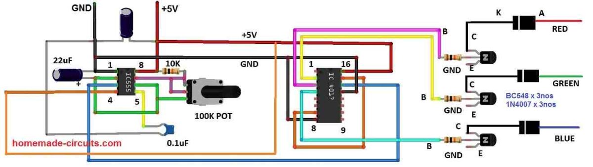
PC cabinet RGB strip controller circuit: Static illumination
The proposed circuit is segregated into multiple sections for better understanding and illustration. The proposed RGB controller for the PC cabinet can illuminate 7 different colors and after the 7th color the strip turns OFF. The circuit shown below is responsible for selecting an illumination color.
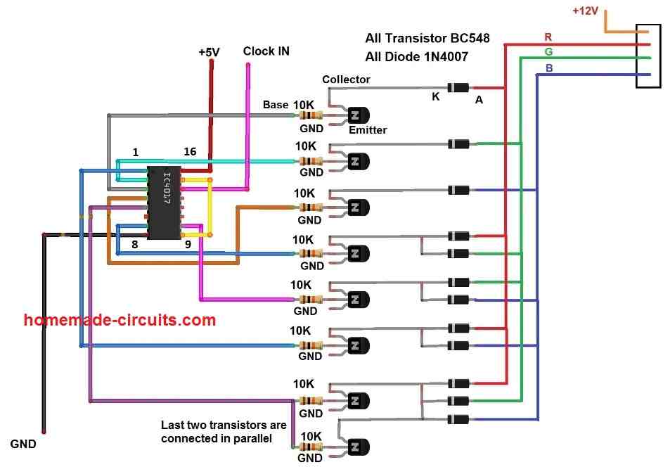
The above circuit consists of IC 4017, bunch of NPN transistors and diodes which are connected to a RGB LED strip. An IC 4017 is employed, which is a Johnson decade counter which can count from 0 to 9 (it can make its output sequentially HIGH according to the incoming clock pulse).
The outputs of IC 4017 are fed to the base terminal of the transistors which will turn ON and OFF specific LED color of the light strip. We can also see there are a bunch of diodes connected to collector terminals, this is for selecting multiple LEDs simultaneously to generate a new color and also to prevent current passing to inactive transistors which will light up unwanted LEDs.
The last two transistors are connected in parallel to create white color, since it needs to illuminate all the LEDs in a strip which will demand a larger current. If you have an RGBW light strip you may connect the last transistor to white LED terminal.

The above circuit is responsible for providing a proper clock signal to IC 4017 which in turns changes the LED illumination color. The above circuit is a monostable multivibrator / debouncing stage which takes a (noisy) negative pulse from the push button and gives out a clean HIGH signal for a pre-determined period of time, so that the IC 4017 won’t register multiple button presses or skip some colors.
A potentiometer is provided to adjust the output timing and please try to keep the pulse at pin #3 between 0.5 to 1 second for optimum operation.
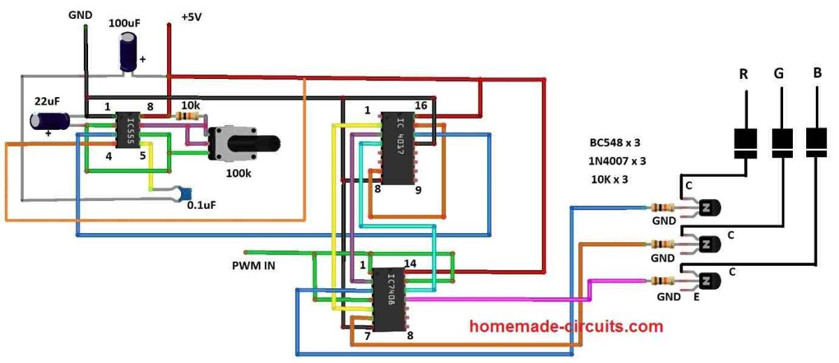
Incorporating brightness control:
Many PC enthusiasts will love to have brightness control for their RGB light illumination, using the below shown circuit modification one can achieve variable brightness control.
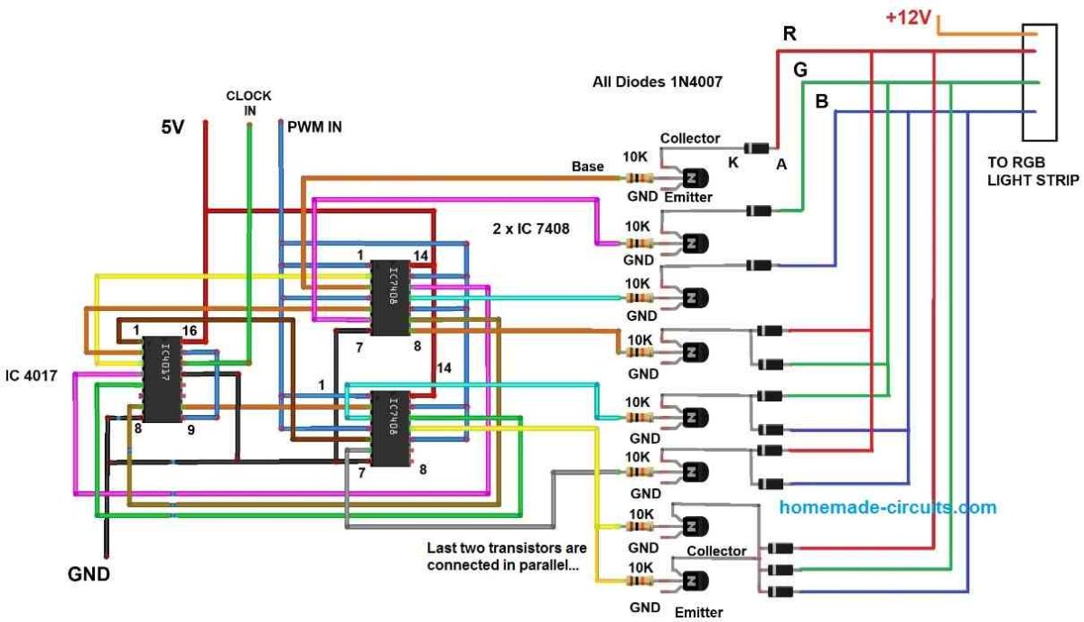
The above circuit is employed with a couple of logic AND gates, the upper one controls the upper four transistors and lower AND gate controls the rest of the three transistors. One of the inputs of all AND gates are tied together and connected to a PWM source. The other inputs of all AND gates are connected to IC 4017’s output for selecting an illumination color.
NOTE: Please note that the above circuit also needs the debouncing stage for button input.
PWM source:
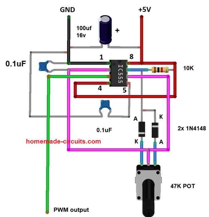
The above circuit generates a PWM signal which will be fed to AND gate. By adjusting the provided 47K potentiometer you can adjust the brightness of the LED strip.
Running light for PC cabinet:
If you are not a fan of static illumination of LED light strips, you can try this circuit which flashes red, green and blue.
The circuit is very easy to build; it has an astable multivibrator using IC 555 and IC 4017 to flash between red, green and blue. The astable multivibrator circuit generates a steady clock pulse which is fed to IC 4017. Every time when the IC 4017 receives a clock signal the output will be switched to a new color.
You can set how fast switching of RGB color you want by adjusting the 100K potentiometer.
Incorporating brightness control:
The above circuit is same as the previous one, only the difference is the addition of logic AND gate. There are four AND gates in the IC 7408 and we are utilizing three of them. One of the AND gate input of all three gates are tied together and connected to a PWM source and the other three inputs are for selecting illumination color.
IR controlled RGB light strip: (for general purpose)
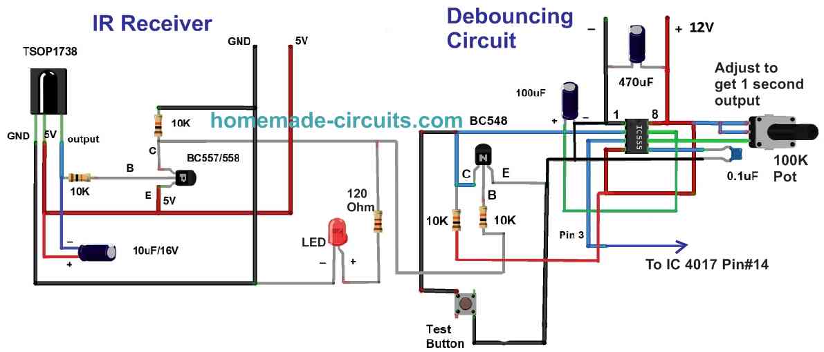
The above circuit is an IR receiver stage which can detect IR signals from any commonly used IR remote controllers.
When an infrared signal is targeted towards the circuit, the incoming signal will be picked by TSOP1738 and converted to pulsating electrical pulses; the pulses are encoded with information which is irrelevant for this project, so we are using a capacitor to smooth it out.
The output after smoothing is feeble and needs amplification, to accomplish this we are using a low power PNP transistor. A LED is connected to the IR stage which indicates that the IR signal has been detected.
The amplified output is fed to a debouncing circuit which gives out a steady HIGH signal to the next stage. The purpose of debouncing circuit is to pick the received signal from the IR stage which could be noisy and gives a smooth output signal, thus noise and unintended multiple button clicks are eliminated.
The clock signal from the debouncing stage is fed to pin 14 of IC 4017 which will switch the light strip’s illumination color. By pressing any button on the IR remote you can switch to your desired illumination color, after white color which is the last one you can turn off the LEDs in the light strip and by pressing a button on the remote we can cycle through all the colors again.
How to smoothly transition between colors?
We can smoothly transition between Red, Green and Blue colors by utilizing a capacitor with appropriate values (220uF to 1000uf) connected to the collector terminal and +12V. This will eliminate abrupt change of colors and also looks pleasant to our eyes.
Note 1: The control circuitry works on 5V and the LED light strip works on 12V, meaning you need a dual power supply.
Note 2: If you are decorating your PC cabinet with RGB, do not power the control circuit or the RGB LED strip from the computer's SMPS, power it from an external wall adapter.