In this post I have explained how to build 7 types of easy sawtooth generator circuits, using BJTs, UJTs, and IC 555.
In a sawtooth waveform the voltage increases slowly in a slanting manner or diagonally, then as soon as it reaches the peak, the waveform voltage suddenly drops to zero. Once it drops to zero, it again starts climbing slowly to repeat the process.

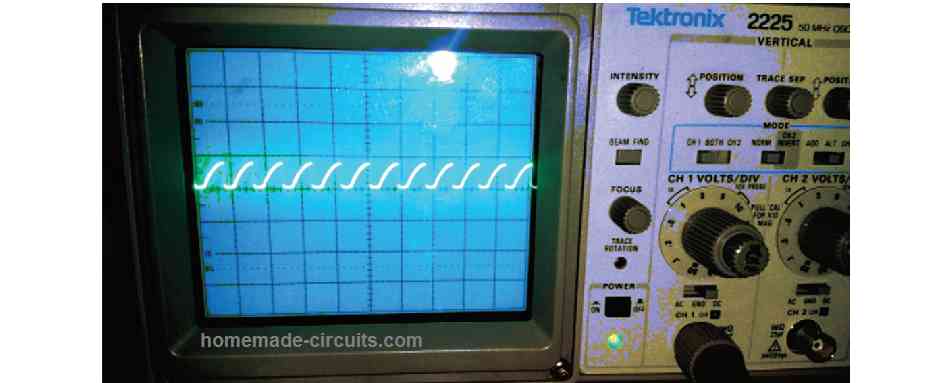
The waveform is named sawtooth, since its appearance resembles the teeth of a sawtooth cutter device.
The above explained sawtooth waveform could be given an opposite shape by generating the waveform in an opposite manner. Here, the waveform voltage first increases suddenly or instantly to the peak value, then falls slowly in a slanting shape until it reaches the zero mark, and then again rises suddenly to the peak value, and this keeps repeating.
When a sawtooth waveform is triggered intermittently, or momentarily or in a one-shot manner, then it is called a ramp waveform.
In the following article I will elucidate simple circuits using IC 555 to generate sawtooth waveform as well as ramp waveform.
Applications
- Sawtooth waves are notable for their application in audio systems.
- The sawtooth and square waves are particular waveforms accustomed to generate audio frequencies with subtractive analog and virtual analog music synthesizers.
- Sawtooth waves are employed in switched-mode power supplies or SMPS designs for implementing output correction.
- In the SMPS regulator IC the error signal in the form of feedback loop, extracted from the output is consistently compared with a high frequency sawtooth to produce an appropriately corrected PWM signal at the output of the error amp circuit or the comparator.
- The sawtooth waveform is processed as vertical and horizontal deflection signals for creating a raster on cathode-ray-tube television or monitor screens.
- Sawtooth wave also find their application in oscilloscopes for their horizontal deflection, although they generally work with electrostatic deflection.
1) Simple Sawtooth Generator using Transistors and UJT
An astable multivibrator, is one of several circuits that can be designed to create sawtooth waveforms. This can, for instance, create negative-going sawtooth waves at the bases of transistors Q1 and Q2 both. As a result, the astable multivibrator may be thought of as just another sawtooth generator that runs indefinitely.
Likewise, throughout their ON time periods, the monostable multivibrators form a negative going sawtooth on the base of Q2. These can work like sawtooth generators with a triggered design.
Since each of their timing capacitors charges exponentially (instead of linearly) via their timing resistors, astable designs produce somewhat nonlinear sawtooth waveforms. Replace each timing resistor with a constant-current generator capable of generating linear waveforms to eliminate this anomaly.
The suitable method to make positive-going triggered sawtooth waveforms is to use a timing circuit designed around a 555-type timer IC.
Nevertheless, a unijunction transistor (UJT) wired in the circuit depicted in the figure below, could be used to produce a free-running, positive edged sawtooth waveforms.
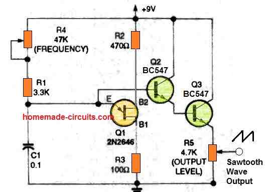
The UJT is actually a 3-terminal transistor with emitter (E), base 1 (B1), and base 2 (B2) connections (132). The supply is connected to the emitter pin of a UJT, which is attached as Q1 in the above figure, with its B2 positive with respect to B1. Until the input (emitter) voltage reaches a particular firing voltage, the UJT Q 1 emitter continues to provide a very high impedance.
That was the time. The status of UJT Q1 unexpectedly changes to ON. The emitter has a low input impedance and drains a lot of current from the input circuitry as soon as it's turned on. If, on the other hand, the input current drops below a particular limit, UJT Q1 returns to its high input impedance condition immediately.
Figure 12 illustrates this. Using trimmer potentiometer R4 and R1, capacitor C1 charges progressively towards the positive supply voltage until the voltage on C1 approaches the UJT Q1 firing threshold. The Q1 turns on at that point, sharply discharging C1.
Once C1 has been discharged. Q1 is turned off once more. As a result, C1 begins to recharge via R4 and R1. With the value of capacitance C1 indicated, this circuit provides a steady yet nonlinear sawtooth waveform which may be adjusted from 25 Hz to 3 kHz by R4. A Darlington emitter-follower buffer stage is formed by connecting transistors Q2 and Q3.
An output terminal obtained via the slider of output level potentiometer R5 receives a low-impedance sawtooth waveform as a result of this arrangement.
2) Variable Sawtooth Generator Circuit
The next figure below depicts the updated circuit.
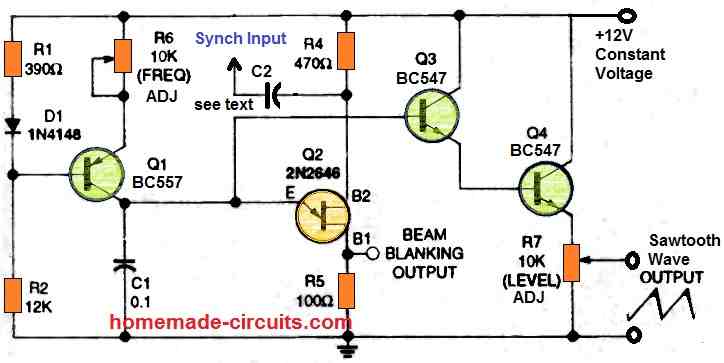
A constant-current source charges capacitor C1. Q1 serves as a thermally compensated, constant-current generator in this circuit. The frequency trimmer potentiometer R6 may be adjusted to change the current from 35 to 390 microamperes.
The linear sawtooth can be used to generate a variable output, with the amplitude controlled by the level control potentiometer R7. When all of the parameters are done as depicted, the working frequency of the above circuit could be adjusted between 60 to 700 Hz using R6.
By changing the value of capacitor C1, you may get different frequency ranges. By supplying an external signal to UJT Q2 via the synch input capacitor C2, the time-base generator may be synchronized to an external signal. The supply voltage (and hence the trigger point) of UJT Q2 is successfully modulated by this external signal, that should have a maximum amplitude somewhere between 200 millivolts and 1.0 volt.
It forces UJT Q2 to exhaust at the same time as the external trigger signal. At the sync signal frequency, capacitor C2 should have a smaller impedance than the resistor R4. Furthermore, the operating voltage of capacitor C2 has to be larger than the external voltage on which the external signal is supplied. The C2 value only has to be some few hundred picofarads in case the sync signal has a rectangular shape with quick rise and fall duration.
3) Nonlinear Sawtooth waveform
The 555 along with some external parts can be converted into a triggered nonlinear sawtooth waveform generator, as demonstrated in the diagram below.
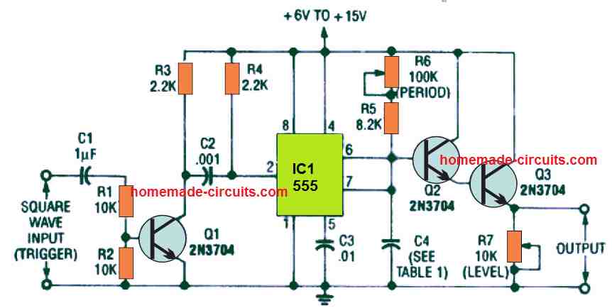
The circuit is actually a customized monostable multivibrator which is activated through an external square wave TRIGGER at pin 2, which is acquired via capacitor C2 through the collector of Q1 transistor.
Notice that IC 555 pin 3 which is commonly used as the output in most IC 555 based circuits is actually empty and unconnected here. The voltage around C4 (which works like the timing component) is generally zero, however the moment the IC 555 is triggered, C4 begins charging exponentially via resistor R5 and TIME PERIOD potentiometer R6 to a level of 2/3rd of the supply voltage.
During this period, the monostable period comes to an end and the voltage across C4 declines suddenly to zero.
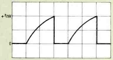
This gives rise to the output sawtooth waveform as shown above, across capacitor C4 by means of Q2, Q3 buffer transistors, and LEVEL control potentiometer R7.
The sawtooth waveform period or pulse width could be adjusted right from 9 microseconds to 1.2 seconds using the capacitors for C4 as detailed in Table 1 below.
| Time Period | Capacitor (C4) |
|---|---|
| 9 µs | 130 pF |
| 20 µs | 290 pF |
| 50 µs | 720 pF |
| 100 µs | 1.44 nF |
| 500 µs | 7.22 nF |
| 1 ms | 14.4 nF |
| 10 ms | 144 nF |
| 50 ms | 720 nF |
| 100 ms | 1.44 µF |
| 500 ms | 7.22 µF |
| 1.2 s | 17.3 µF |
The circuit's highest functional repetition frequency is around 100 kHz. The sawtooth generator should be activated or triggered with input waveforms having rectangular shape and with quick rise and fall periods.
Potentiometer R6 is used for controlling the sawtooth time period through a resistor decade, and potentiometer R7 is wired to controls the amplitude of the output waveform.
4) Linear Sawtooth Ramp Waveform Generator
The next diagram below exhibits a induced linear sawtooth or ramp waveform generator. Capacitor C4 is charged through a constant-current source built around the transistor Q1 stage.
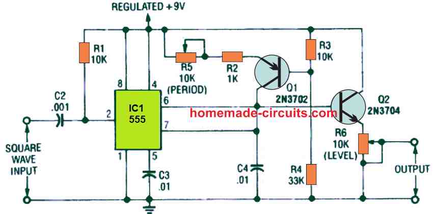
The output linear sawtooth waveform or the ramp waveform as shown below is obtained from the slider arm of the LEVEL potentiometer R6, that is connected across the capacitor C4 via Q2.
Observe that the rounded ramps in the earlier waveform happen to be flattened or compressed in the below shown linear sawtooth waveform.
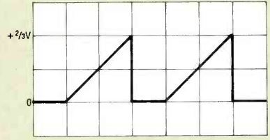
As soon as a capacitor C4 is charged through a constant current source, the voltage across it goes up with a consistent linear rate which can be depicted with the equation:
Volts/second = amperes/farad
Through the introduction of further simple values, alternate equations for the rate of voltage rise can be given as:
V/µs = A/µF, or V/ms = mA/µF
The above equations suggest that the rate of voltage rise could be higher either by increasing charging current for the C4 or by decreasing the C4 value.
The charging current in the second sawtooth generator circuit above could be changed, by a measure from 90 microamperes to 1 milliampere using the PERIOD potentiometer R5. This would result in a 0.01 microfarad timing capacitor producing a rates-of-rise of 9 volts per millisecond to 100 volts per millisecond.
Every one-shot or monostable cycle of the 555 comes to an end as soon as the voltage across C4 attains 2/3rd of the supply voltage. As displayed in the second linear sawtooth generator circuit, the input supply is 9 volts, which means 2/3rd of 9 volts will be 6 volts, and the the ramp voltage amplitude waveforms will be as shown above.
The sawtooth waveform of the circuit include periods that can be varied from 666 microseconds (2/3 millisecond) to 60 microseconds (6/100 millisecond). It is possible to increase this intervals beyond the above values by increasing the value of C4, or the values could be lowered by lowering the C4 value.
In the proposed sawtooth generator circuit, stable timing intervals is strictly dependent on a stable voltage source.
5) Oscilloscope Time-base Generator
The next figure below indicates how the earlier linear sawtooth generator circuit could be customized for being an oscilloscope time-base generator.
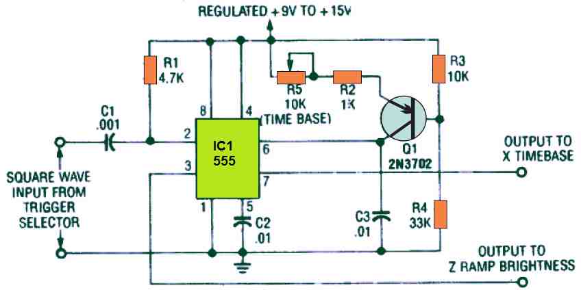
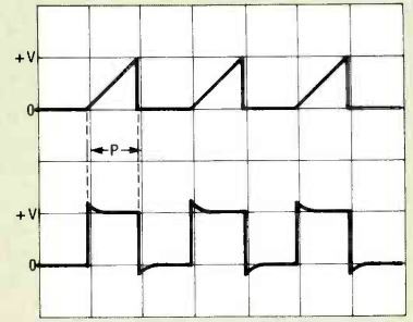
It could be activated through external square waves, by using an appropriate trigger selector circuit. The upper ramp output waveform is connected to the X axis of an oscilloscope using a good amplifier stage.
The timebase circuit as shown in the above figure can coordinate signals with trigger frequencies upto 150 KHz. At increased frequencies, the input signals should be broken down by a single-or multi-decade frequency divider. With this strategy, the timebase could be implemented to view input signals at megahertz frequencies
Trigger Selector
The figure below shows a straightforward yet multipurpose trigger selector circuit for the timebase generator as explained in the pervious paragraph.

Op amp IC1 (a µA741) provides a reference voltage applied to its non-inverting input pin 3 through TRIGGER LEVEL potentiometer R4. The signal voltage is subsequently fed to IC1's inverting pin 2 via switch S1, resistor R1 and SENSITIVY potentiometer R3.
Switch S1 chooses either in-phase or out-of-phase input signals from the Y-channel amplifier driver for the oscilloscope, enabling the range of either the plus or minus trigger modes. The output from the IC 741 is connected straight to the C1 input of the earlier time base generator circuit.
6) Simplified Non-Linear Sawtooth Generator Circuit
The following figure exhibits the design of a extremely straightforward non-linear sawtooth waveform generator that is actually simply a Standard 555 astable.
Nevertheless, the resistance which can be seen connected between pins 6 and 7 of the IC 555 is made zero to ensure that timing capacitor C1 is discharged practically instantaneously as soon as its charge voltage extends to the 2/3 V limit.
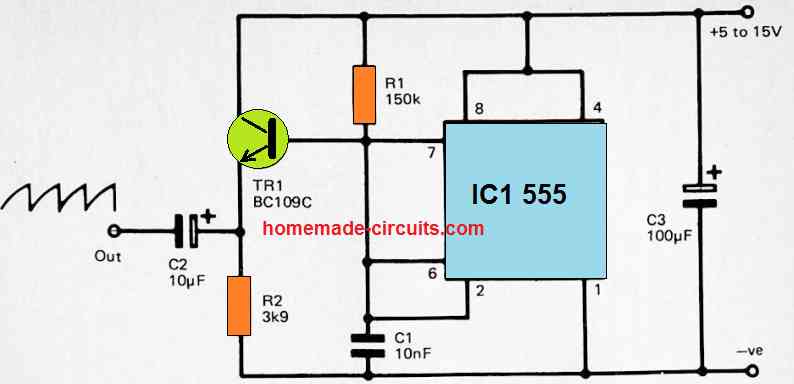
The sawtooth waveform is actually extracted across the capacitor C1, while the short negative pulses available at pin 3 of the IC1 is not used. Tr1 and R1 are configured like a simple emitter follower buffer stage in order to achieve a fairly low output impedance via the high impedance signal across C1.
The indicated values offer an running frequency of approximately 1kHz (960Hz through calculations). That said, the R1, and C1 values might certainly be altered to provide a new output frequency.
It is recommended to avoid making R1 too much bigger than the chosen value of 150k, otherwise loading on the timing circuitry might stop the sawtooth waveform generation from performing correctly.
7) Simplified Linear Sawtooth Generator Circuit
In the previous diagram we saw how to configure a non-linear sawtooth genertaor. In the next concept I have explained how to build a linear sawtooth geneator circuit using the IC 555.
A linear sawtooth waveform could be easily created by enabling the charging of C1 through a constant current source in order that the voltage across C1 increases with a constant rate.
The following figure exhibits a straightforward circuit of a linear sawtooth generator, which is an almost exact replica of the previous design except the timing resistor which has been replaced with a standard constant current source through the Tr2 network.
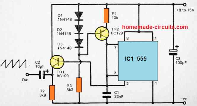
The circuit functions at approximately 1kHz using the selected values for R1 and C1. However, it is possible to adjust the output frequency by varying the values of either R1 or C1. R1 must be selected between Ik and 47k range for getting optimal response from the circuit.
Hi,
In the second circuit you mention to see table 1 for the values of C4 but there is no Table 1.
Can you clarify this?
Thanks.
Best Regards.
Nélio
Thank you for notifying about the issue.
I have updated the table now, you can check it out.